Power Brake Booster - Operation
OPERATION
WITHOUT 5.7L HEV
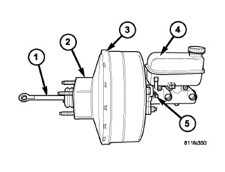
The booster unit consists of a single housing divided into two by a tandem diaphragm (3). The outer edge of the diaphragm is secured to the housing. A spacer block (2) is located in between the cowl and the booster housing. The booster push rod (1), connects the booster to the brake pedal and master cylinder (4), is attached to the center of the diaphragm. A check valve (5) is used in the booster outlet connected to the engine intake manifold. Power assist is generated by utilizing a combination of vacuum and atmospheric pressure to boost brake assist.
WITH 5.7 HEV
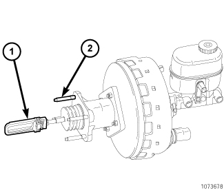
NOTE: The active brake booster and it's components are serviced as an assembly only. The master cylinder may be replaced separately or as a unit with the active brake booster.
The 5.7L HEV active booster has a different design for the booster push rod (1) and uses only three retaining studs (2) and 1 unused stud. The booster push rod (1) connects the booster to the brake pedal and master cylinder and is attached to the center of the diaphragm. A replacement active booster will have a new spacer block and booster push rod with a preset adjustment which should not be changed. A check valve is used in the booster outlet connected to the engine intake manifold and a vacuum pump. Normal power assist is generated by utilizing a combination of vacuum and atmospheric pressure to boost brake application. The 5.7L HEV active booster has a unique operation designed for charging assist of the 300 V battery system. On braking applications the internals of the booster are not directly connected and the booster to master cylinder push rod will not actuate the master cylinder/standard braking system. Under these conditions braking is accomplished through the electric motors within the transmission. If more braking is necessary the active booster can utilize the vacuum supplied by the vacuum pump to actuate the master cylinder. These controls are determined by the antilock brake control (ABS) module (regenerative brake system [RBS]), and under a fault condition concerning regenerative braking, normal vehicle braking takes. There will be slightly more pedal travel when active braking defaults to mechanical/standard braking.
Below are the active brake booster specific components.
- ACTIVE BRAKE BOOSTER SOLENOIDThe active brake booster solenoid allows the ABS module to actuate the brake booster and apply hydraulic brake pressure via the brake master cylinder without a mechanical link between the brake pedal and booster. The solenoid is controlled via a PWM ground signal from the ABS module. When the solenoid is activated, atmospheric pressure is allowed on the rear side of the booster and vacuum is allowed on the front side of the booster to move the master cylinder piston to apply the hydraulic brakes.
- BOOSTER TRAVEL SENSORThe travel sensor is a three-wire potentiometer that varies the voltage output as the position of the booster diaphragm changes. The RBS module uses the position information to determine the amount of booster movement and hydraulic brake application.
- BOOSTER VACUUM SENSORThe vacuum sensor consists of two signal circuits (redundant for safety) for calculation of brake system operation requirements by the RBS.
- PRIMARY PUSH RODThe primary push rod is redesigned so the ABS module and active booster will control the hydraulic brakes while the brake pedal simulator unit will operate to give a normal brake pedal feel.