- Raise and support vehicle. Refer to STANDARD PROCEDURE
.
 Courtesy of CHRYSLER LLC
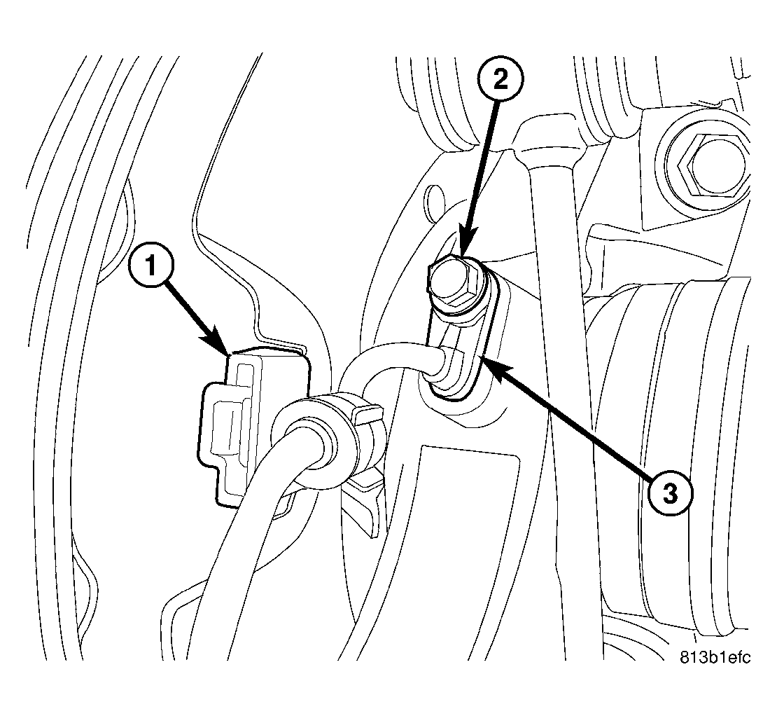
- Unclip wheel speed sensor cable at rear brake rotor shield (1).
- Remove screw (2) fastening sensor head (3) to rear knuckle.
- Remove wheel speed sensor head from knuckle.
- Access and remove rear hub and bearing. See REMOVAL .
- Remove parking brake shoes. Refer to REMOVAL
.
 Courtesy of CHRYSLER LLC
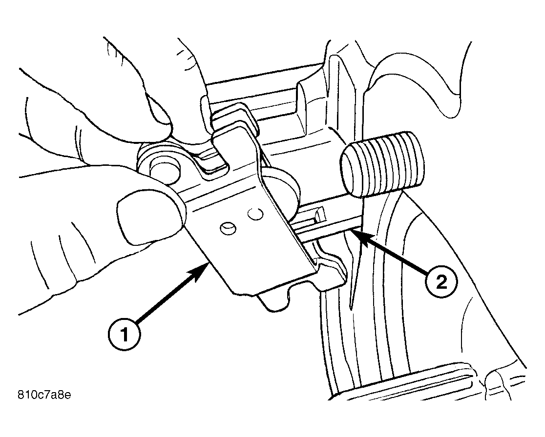
| 1 - PARKING BRAKE SHOE ACTUATOR |
| 2 - CABLE END |
- If not removed, remove parking brake shoe actuator lever (1) from end of cable (2).
- Remove shoe support from knuckle.
 Courtesy of CHRYSLER LLC
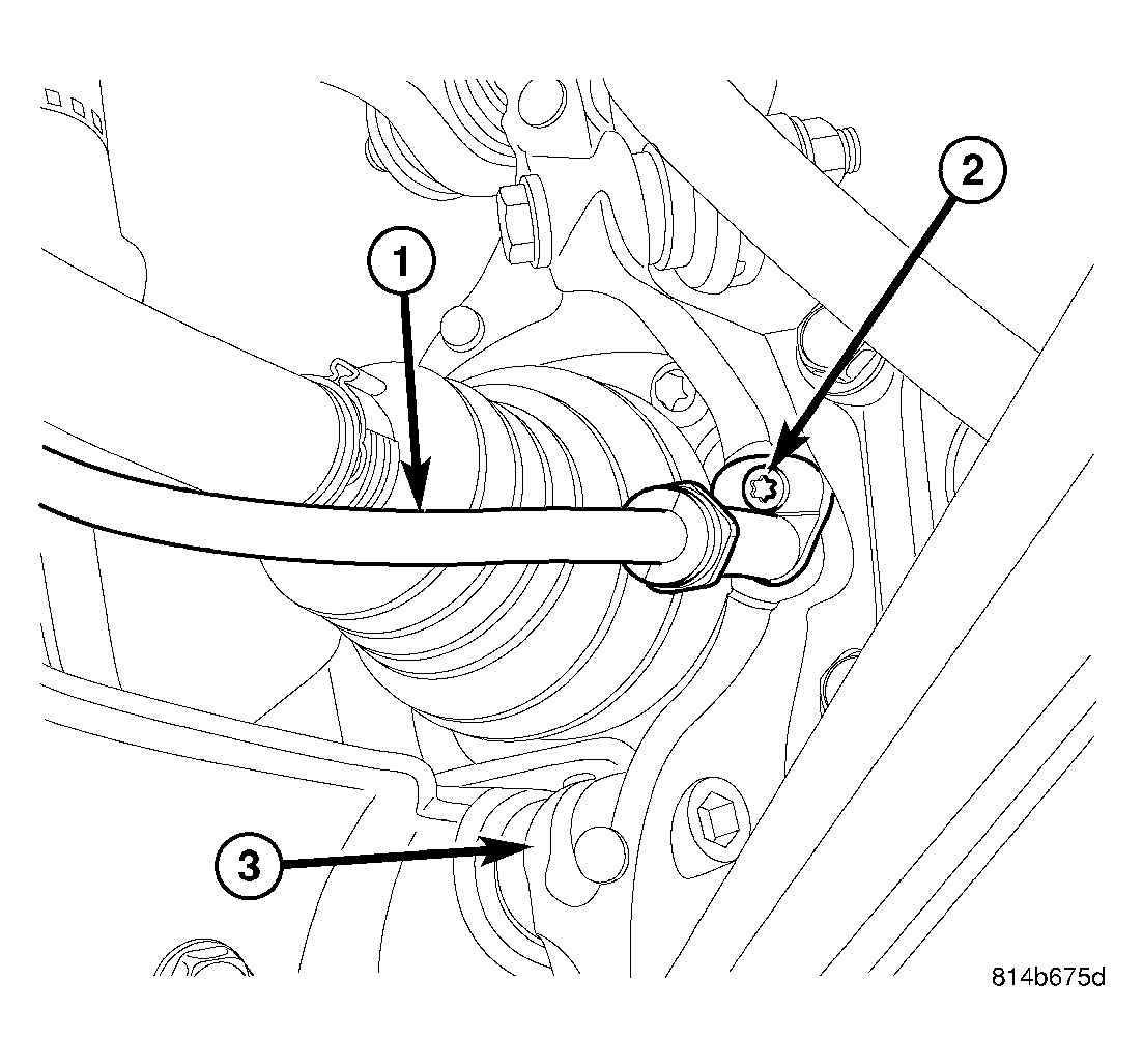
- Remove parking brake cable screw (2) at knuckle (3) and pull cable (1) out of knuckle.
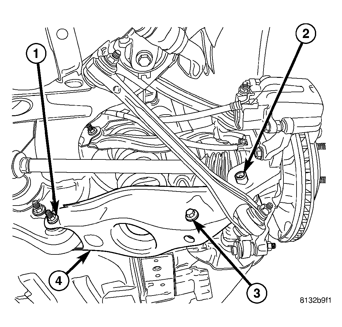
- Position under-hoist utility jack or jack stand under spring link. Raise jack head to contact spring link at shock mount secure in place.
 Courtesy of CHRYSLER LLC
- Remove spring link-to-knuckle nut and bolt (2).
 Courtesy of CHRYSLER LLC
CAUTION:
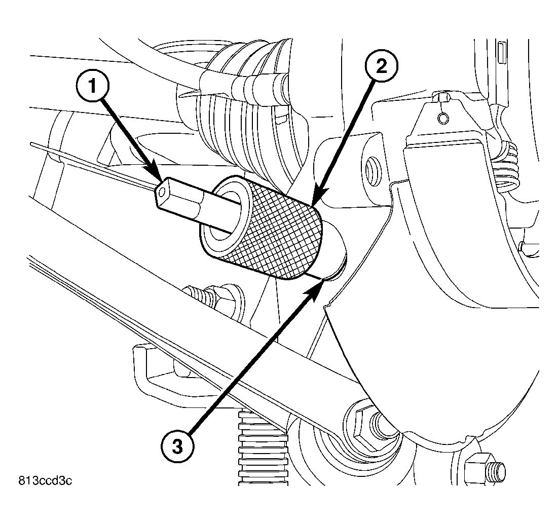
It important to use Guide (2) , Special Tool 9361-2, when tapping sleeve in knuckle to help keep Tap (1) , Special Tool 9361-1, straight during use or damage to Tap may occur.
- Place Guide 9361-2 (2) against sleeve (3) in knuckle to keep Tap 9361-1 (1) straight. Using Tap with an appropriate handle, cut threads approximately halfway through bushing (or about six complete threads). It is important to back tap out, clean out burrs and lubricate Tap often during process.
 Courtesy of CHRYSLER LLC
NOTE:
Prior to using Special Tool 9361, lubricate Bolt (1) threads to provide ease of use and promote tool longevity.
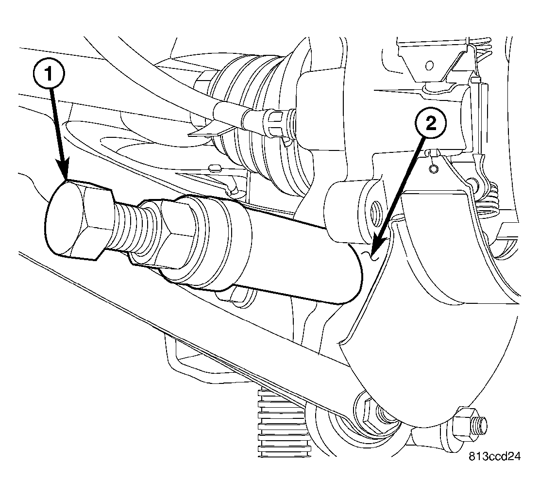
- Assemble Remover, Special Tool 9361, as shown.
- (1) Bolt 9361-3
- (2) Nut
- (3) Spherical Washer
- (4) Thrust Bearing
- (5) Sleeve 9361-4 (RWD)
- (5) Sleeve 9361-5 (AWD - Left Side)
- (5) Sleeve 9361-6 (AWD - Right Side)
NOTE:
When installing thrust bearing on Remover, be sure to place hardened side against nut. Place bearing outer cage against stationary component.
NOTE:
It is important to use appropriate Sleeve on Remover to provide proper Tool-to-Knuckle contact. RWD sleeve can be used on either side while AWD knuckles require specific left or right side Sleeves.
 Courtesy of CHRYSLER LLC
- Thread Remover Bolt 9361-3 (1) into tapped knuckle sleeve.
- Rotate Nut down, matching Sleeve angled end with angled face of knuckle.
- Continue to rotate Nut until knuckle sleeve is removed from knuckle. Discard knuckle sleeve; replace it with new upon installation.
 Courtesy of CHRYSLER LLC
- Remove bolt and nut fastening compression link (5) to knuckle (4).
- Remove bolt fastening toe link (3) to knuckle (4).
- Remove nut and bolt fastening stabilizer link to knuckle (4).
- Remove nut and bolt fastening tension link (6) to knuckle (4).
- Remove nut and bolt fastening camber link (1) to knuckle (4).
- Remove knuckle (4).
- Remove hub mounting bolts from knuckle.