- If shield needs to be installed on knuckle, place shield in place and attach to knuckle using 3 screws. Tighten screws to 10 N.m (89 in. lbs.).
 Courtesy of CHRYSLER LLC
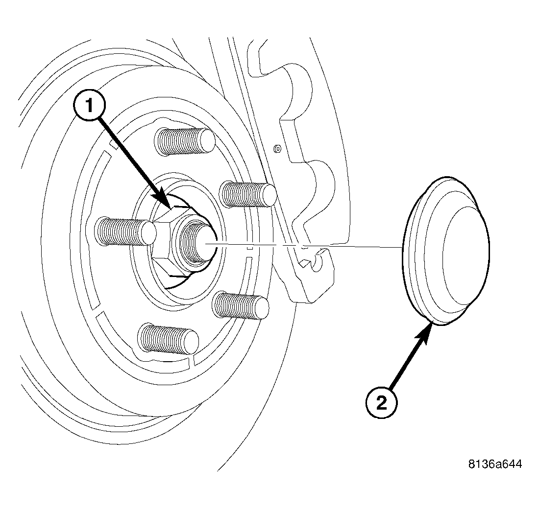
- If hub and bearing needs to be installed on knuckle, perform the following:
- Slide hub and bearing onto knuckle spindle.
- Install hub nut (1) on end of spindle. Tighten hub nut to 250 N.m (184 ft. lbs.).
- Install NEW dust cap (2).
NOTE:
Install a new dust cap to preserve seal integrity.
 Courtesy of CHRYSLER LLC
CAUTION:
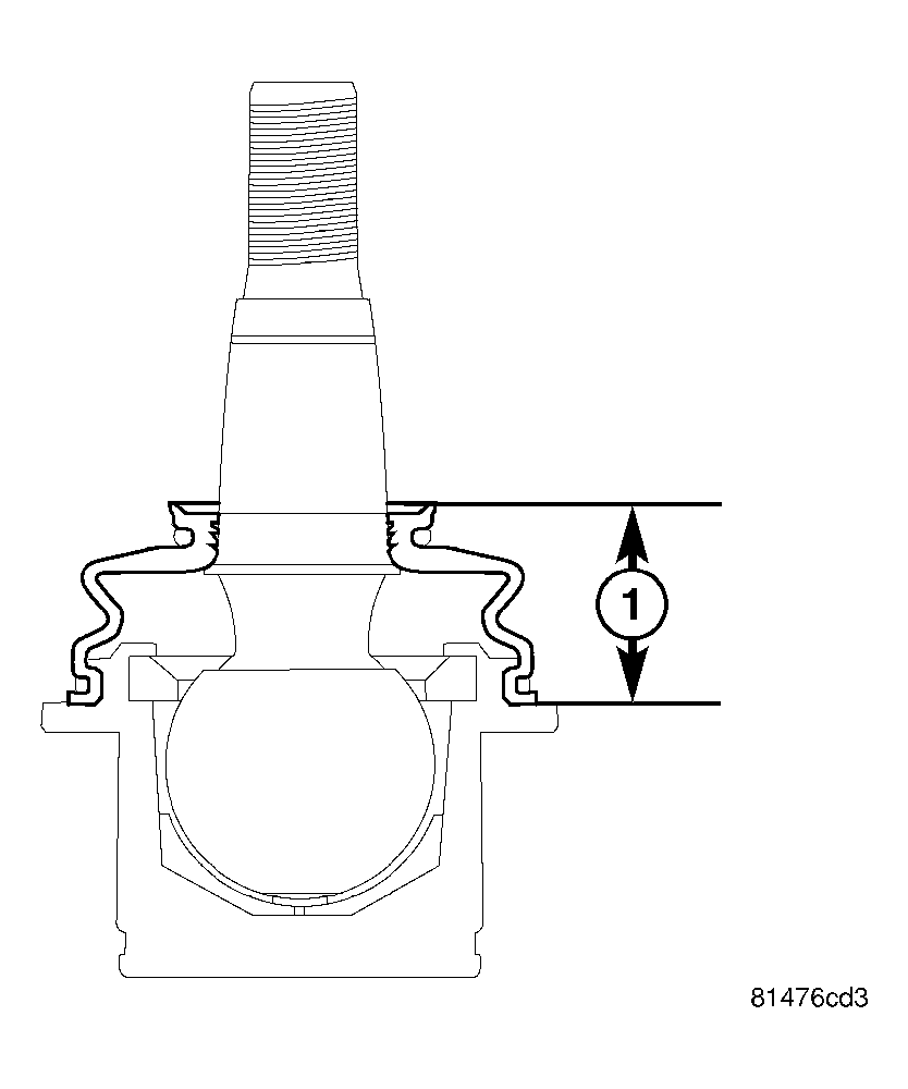
Before installing knuckle on lower control arm, measure height of ball joint seal boot (1) mounted on knuckle. If seal boot height is above 25.5 mm, any air inside seal boot must be expelled. To do so, follow these steps.
- Tip ball joint stud completely to one side.
- Using thumb and index finger, gently squeeze seal boot together at center expelling any air. Do not allow grease to be release.
- Push down very top of seal boot.
- Return ball joint stud to original "centered" position.
- Measure ball joint seal boot height (1) making sure it is within specification.
- Wipe any grease from ball joint stud.
 Courtesy of CHRYSLER LLC
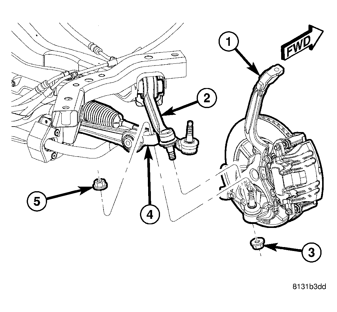
- Place knuckle (1) over lower ball joint studs on vehicle and loosely install NEW nuts by hand.
CAUTION:
It is important to tighten nuts as described in following steps to avoid damaging ball stud joints.
- Completely install NEW nut (5) on ball joint stud attaching lower control arm (4) to knuckle (1). Tighten nut by holding ball joint stud with a hex wrench while turning nut with a wrench. Tighten nut using crow foot wrench on torque wrench to 68 N.m + 90° turn (50 ft. lbs. + 90° turn).
- Completely install NEW nut (3) on ball joint stud attaching tension strut (2) to knuckle (1). Tighten nut by holding ball joint stud with a hex wrench while turning nut with a wrench. Tighten nut using crow foot wrench on torque wrench to 68 N.m + 90° turn (50 ft. lbs. + 90° turn).
 Courtesy of CHRYSLER LLC
CAUTION:
It is important to tighten nut as described in following step to avoid damaging ball stud joint.
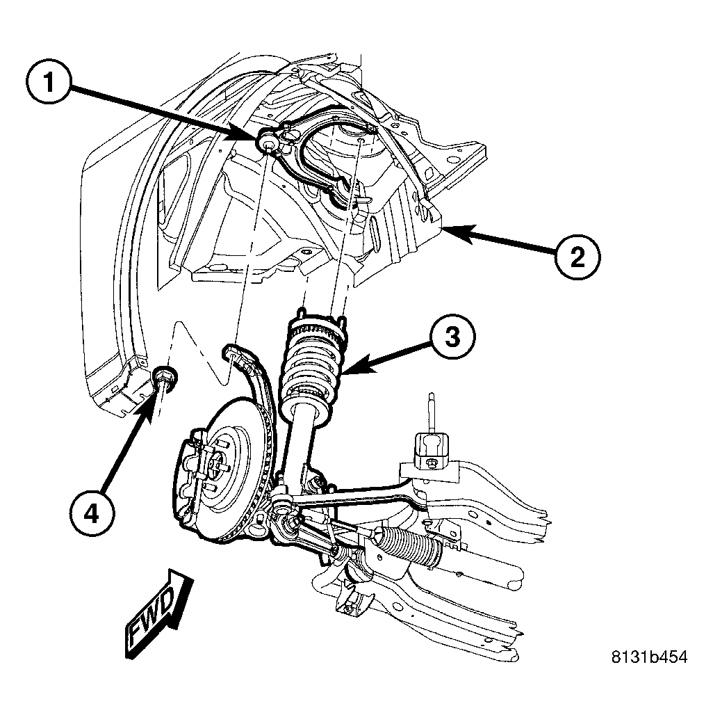
- Place upper ball joint stud (1) through hole in top of knuckle and install nut (4). Tighten nut by holding ball joint stud with a hex wrench while turning nut with a wrench. Tighten nut using crow foot wrench on torque wrench to 47 N.m + 90° turn (35 ft. lbs. + 90° turn).
 Courtesy of CHRYSLER LLC
CAUTION:
It is important to tighten nut as described in following step to avoid damaging ball stud joint.
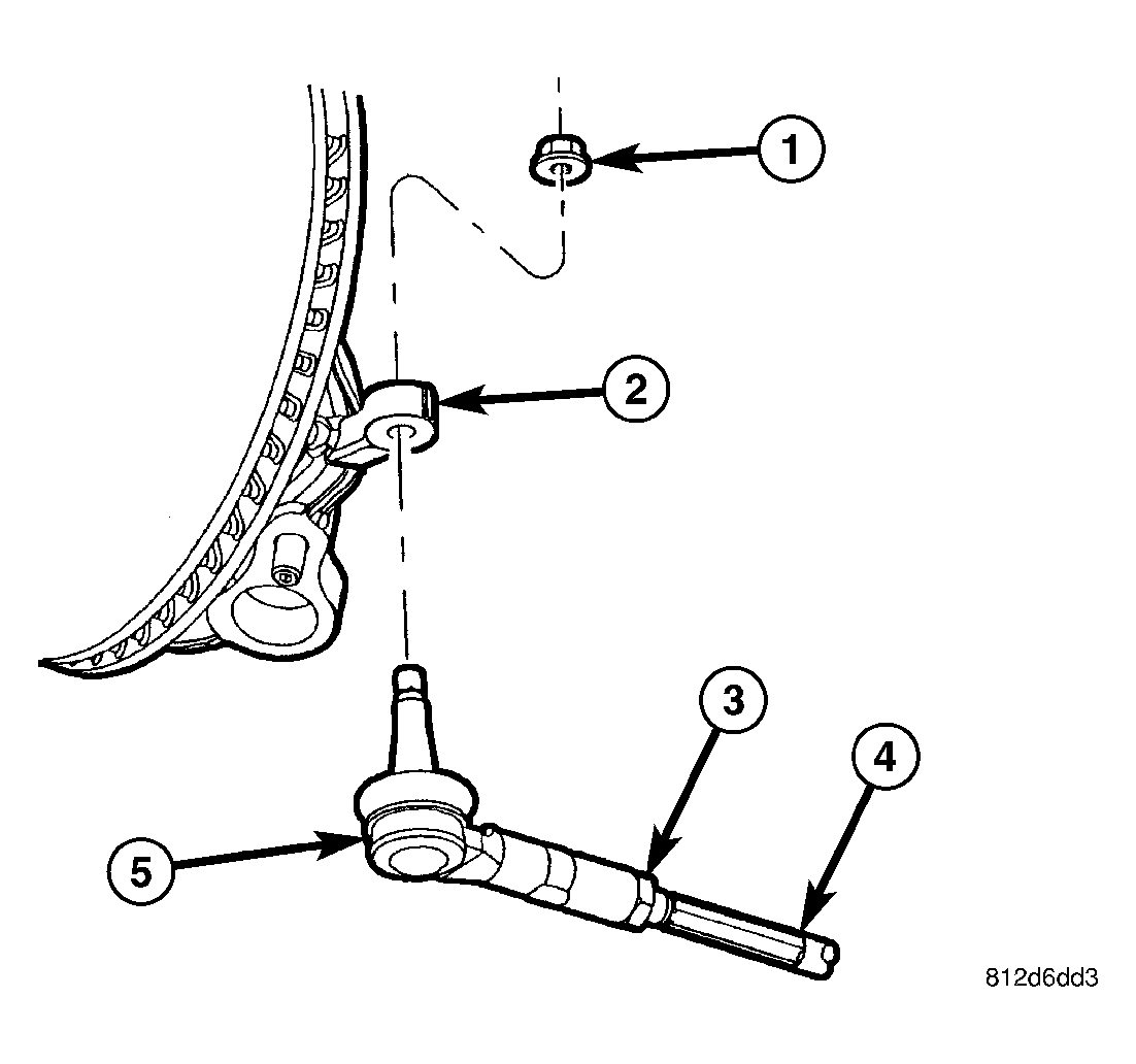
- Place outer tie rod stud through hole in knuckle (2) and install nut (1). Tighten nut by holding stud with a wrench while turning nut with another wrench. Tighten nut using crow foot wrench on torque wrench to 85 N.m (63 ft. lbs.).
- Install brake rotor, then disc brake caliper and adapter assembly. Refer to INSTALLATION
.
 Courtesy of CHRYSLER LLC
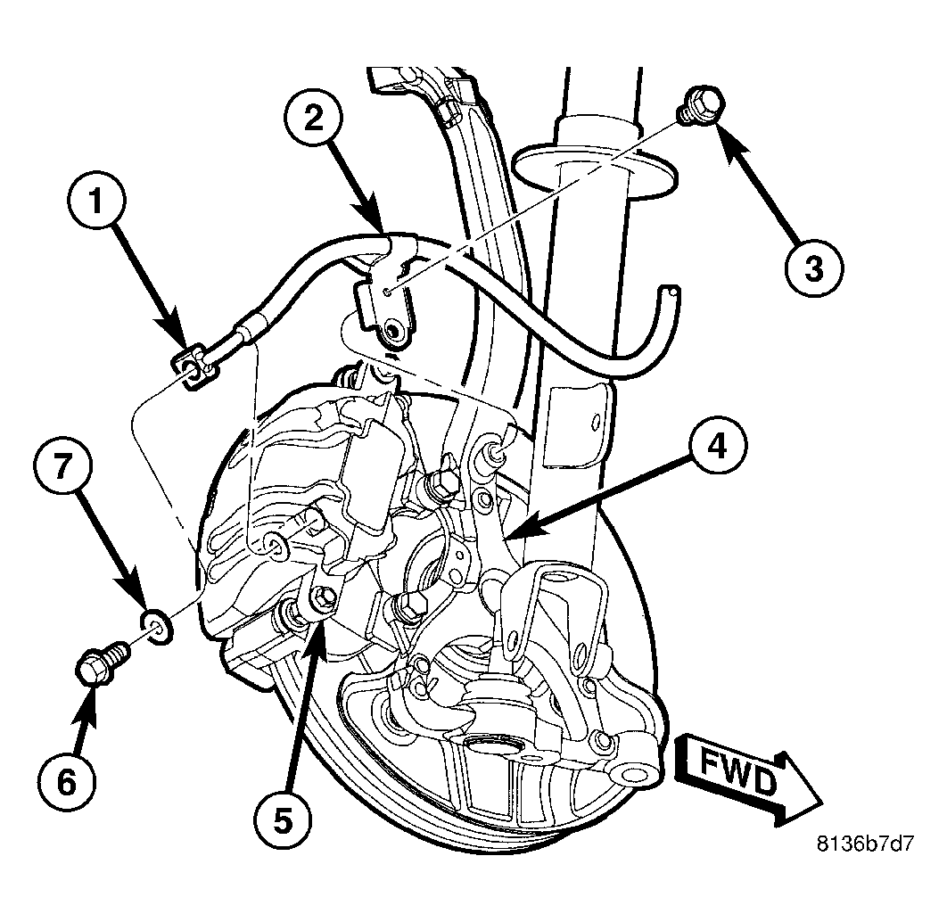
- Install screw (3) fastening brake flex hose routing bracket (2) to knuckle (4). Tighten screw to 12 N.m (106 in. lbs.).
 Courtesy of CHRYSLER LLC
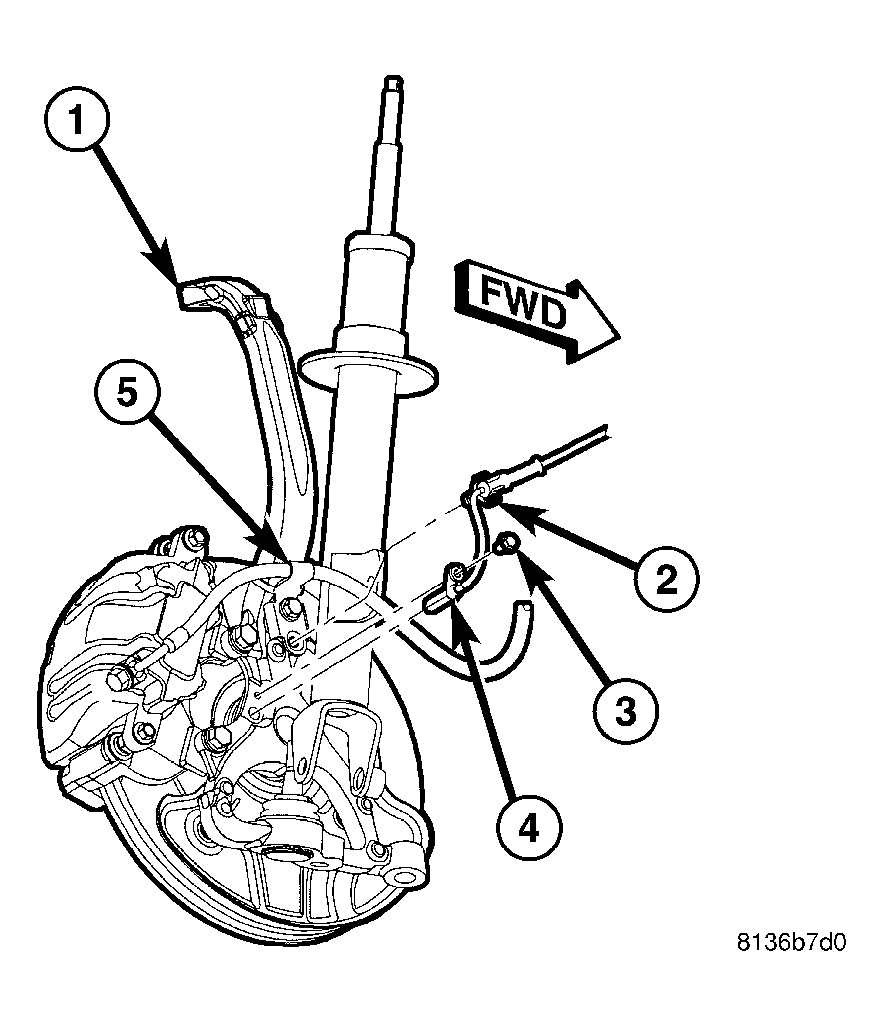
- Install wheel speed sensor head (4) into knuckle and install mounting screw (3). Tighten screw to 11 N.m (95 in. lbs.).
- Attach wheel speed sensor cable and routing clip (2) to brake flex hose routing bracket (5).
 Courtesy of CHRYSLER LLC
- Install tire and wheel assembly (1). Refer to INSTALLATION
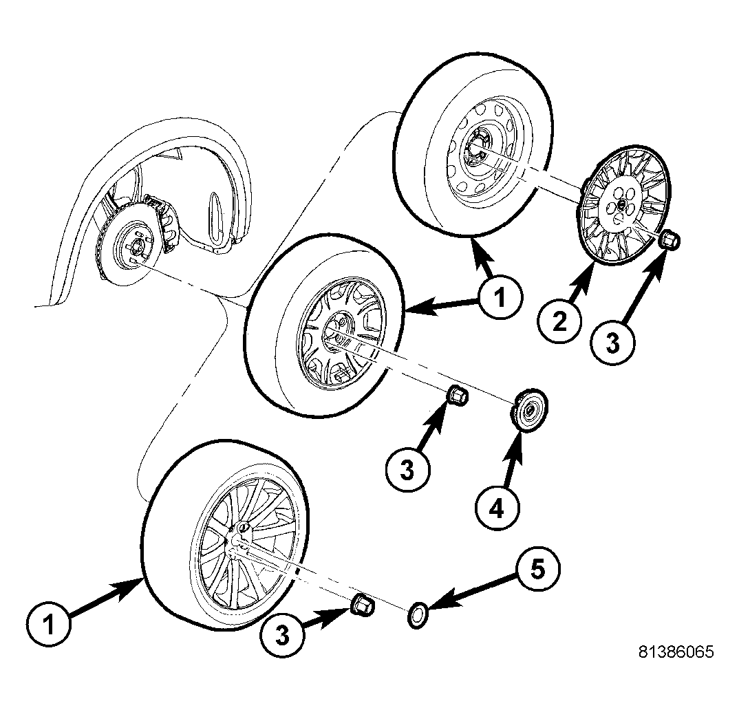
. Tighten wheel mounting nuts (3) to 150 N.m (110 ft. lbs.) (Police - 190 N.m (140 ft. lbs.)).
- Lower vehicle.
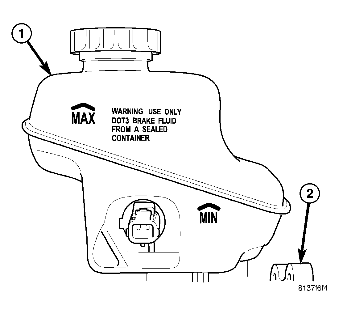 Courtesy of CHRYSLER LLC
- Pump brake pedal several times to ensure vehicle has a firm brake pedal before moving vehicle.
- Check and adjust brake fluid level in reservoir (1) as necessary.
- Perform wheel alignment. See STANDARD PROCEDURE .