Integrated Control Unit (ICU) - Removal
REMOVAL
NOTE: Before proceeding, Technician Safety Information Vehicle Damage Warnings .
1. Remove the air cleaner housing.Air Cleaner Body - Removal
2. Remove the battery. Battery - Removal
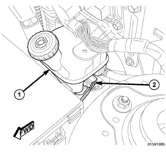
3. Disconnect the vehicle wiring harness connector (2) at the brake fluid level switch in the master cylinder brake fluid reservoir (1).
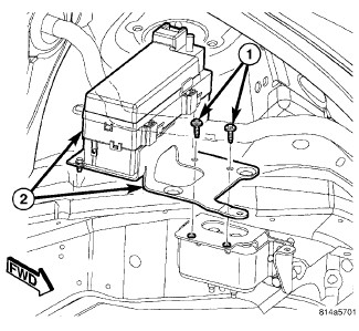

4. Non-Turbo Engine - Remove the two bolts (1) fastening the Totally Integrated Power Module (TIPM) and mounting bracket (2) in place.
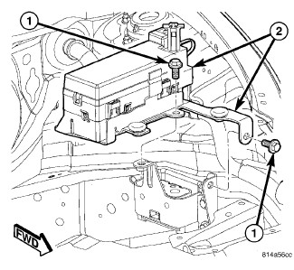

5. Turbo Engine - Remove the two bolts (1) fastening the power distribution center and mounting bracket (2) in place.
6. Lift the TIPM and mounting bracket up and move it to the driver side, out of the way.
7. Clean the area around where brake tubes attach to the ICU hydraulic control unit (HCU) using a suitable brake cleaner such as Mopar(R) Brake Parts Cleaner or equivalent.
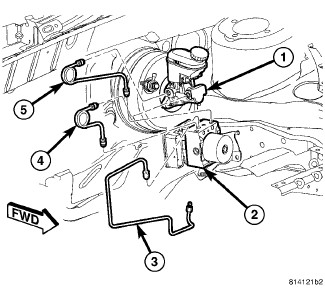
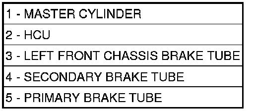
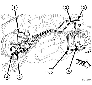
8. LHD Vehicle:
a. Disconnect the primary (5) and secondary (4) brake tubes coming from the master cylinder (1) at the HCU (2).
b. Disconnect the left front chassis brake tube (3) at the HCU (2).
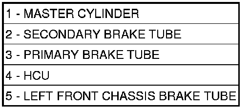
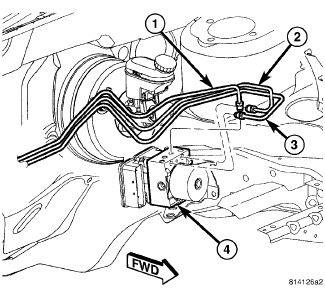
9. RHD Vehicle:
a. Disconnect the primary (3) and secondary (2) brake tubes coming from the master cylinder (1) at the HCU (4).
b. Disconnect the left front chassis brake tube (5) at the HCU (2).
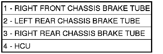
10. Disconnect the right front (1), left rear (2) and right rear (3) chassis brake tubes at the HCU (4).
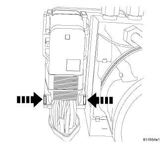
NOTE: Use this figure in the following step to release the ABM harness connector cover. It shows the location of the release tabs.
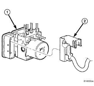
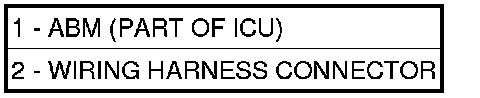
11. Disconnect the ABM harness connector from the antilock brake module (ABM). To do so:
a. Depress the tabs on each side of the connector cover, then
b. Pull outward and upward on the lower half of the cover until it locks into position pointing straight outward (2). The connector can then be pulled straight outward off the ABM (1).
12. Raise and support the vehicle. Maintenance
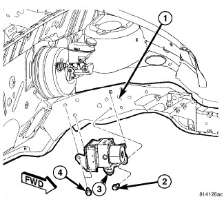
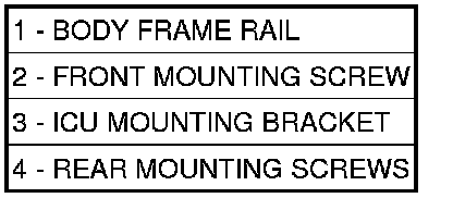
13. Remove the two rear mounting screws (4) attaching the ICU mounting bracket (3) to the body (1).
14. Lower the vehicle.
15. Remove the front mounting screw (2) attaching the ICU mounting bracket (3) to the body (1).
16. Lift the ICU and mounting bracket from the vehicle.
17. To separate the ABM from the HCU, Integrated Control Unit (ICU) - Disassembly.