Integrated Control Unit (ICU) - Installation
INSTALLATION
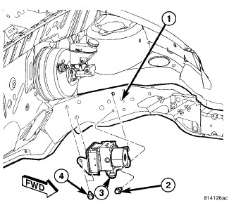
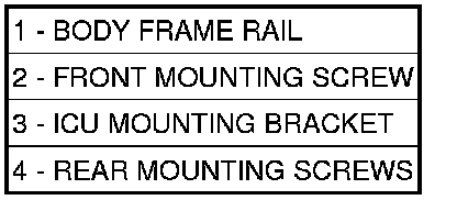
1. Place the ICU and mounting bracket (3) into the engine compartment, inserting the bracket hooks into the hanger holes in the body frame rail (1).
2. Install the front mounting screw (2) attaching the ICU mounting bracket (3) to the body (1). Do not tighten screw at this time.
3. Raise and support the vehicle. Maintenance
4. Install the two rear mounting screws (4) attaching the ICU mounting bracket (3) to the body (1). Tighten both screws to 23 Nm (200 in. lbs.).
5. Lower the vehicle.
6. Tighten the front mounting screw (2) to 23 Nm (200 in. lbs.).
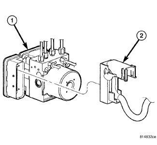
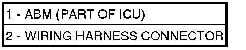
CAUTION: Before installing the ABM harness connector on the ABM, be sure the seal is properly installed in the connector.
7. Insert the ABM harness connector (2) into the socket of the ABM (1) and close the cover, locking the connector in place.
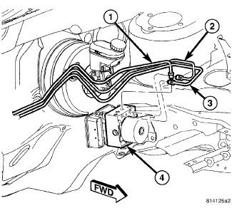
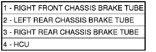
8. Connect the right front (1), left rear (2) and right rear (3) chassis brake tubes to their respective outlet ports on the ICU HCU (4). Using a crow foot wrench on a torque wrench, tighten the four tube nuts to 17 Nm (145 in. lbs.).
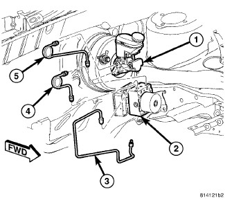
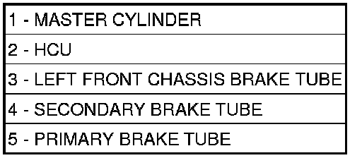
9. LHD Vehicle:
a. Connect the left front chassis brake tube (3) at the HCU (2). Using a crow foot wrench on a torque wrench, tighten the tube nut to 17 Nm (145 in. lbs.).
b. Connect the primary (5) and secondary (4) brake tubes coming from the master cylinder (1) at the HCU (2). Using a crow foot wrench on a torque wrench, tighten the tube nuts to 17 Nm (145 in. lbs.).
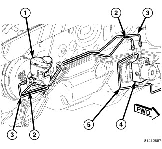
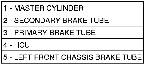
10. RHD Vehicle:
a. Connect the left front chassis brake tube (5) at the HCU (4). Using a crow foot wrench on a torque wrench, tighten the tube nut to 17 Nm (145 in. lbs.).
b. Connect the primary (3) and secondary (2) brake tubes coming from the master cylinder (1) at the HCU (2). Using a crow foot wrench on a torque wrench, tighten the tube nuts to 17 Nm (145 in. lbs.).
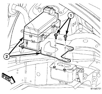

11. Non-Turbo Engine - Position the Totally Integrated Power Module (TIPM) and bracket back into place and install the two bolts (1) fastening the power distribution center and mounting bracket (2) in place.
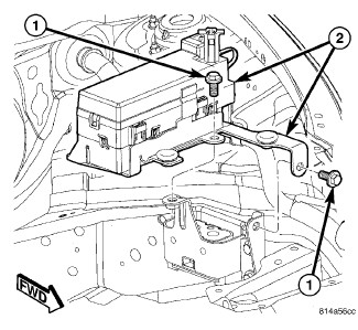

12. Turbo Engine - Position the TIPM and bracket back into place and install the two bolts (1) fastening the power distribution center and mounting bracket (2) in place.
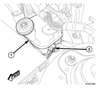
13. Connect the wiring connector (2) to the brake fluid level switch in the brake fluid reservoir (1).
14. Install the battery. Battery - Installation
15. Install the air cleaner housing.Air Cleaner Body - Installation
16. Hook up the scan tool to initialize the ABM and perform the following:
a. Clear any faults.
b. Fill the master cylinder to the proper fill level and bleed the base and ABS hydraulic systems. Service and Repair
c. Perform the ABS Verification Test and road test the vehicle. ABS Verification Test.