B1B79
B1B79-PASSENGER SEAT WEIGHT SENSOR 3 - LEFT FRONT INPUT CIRCUIT LOW
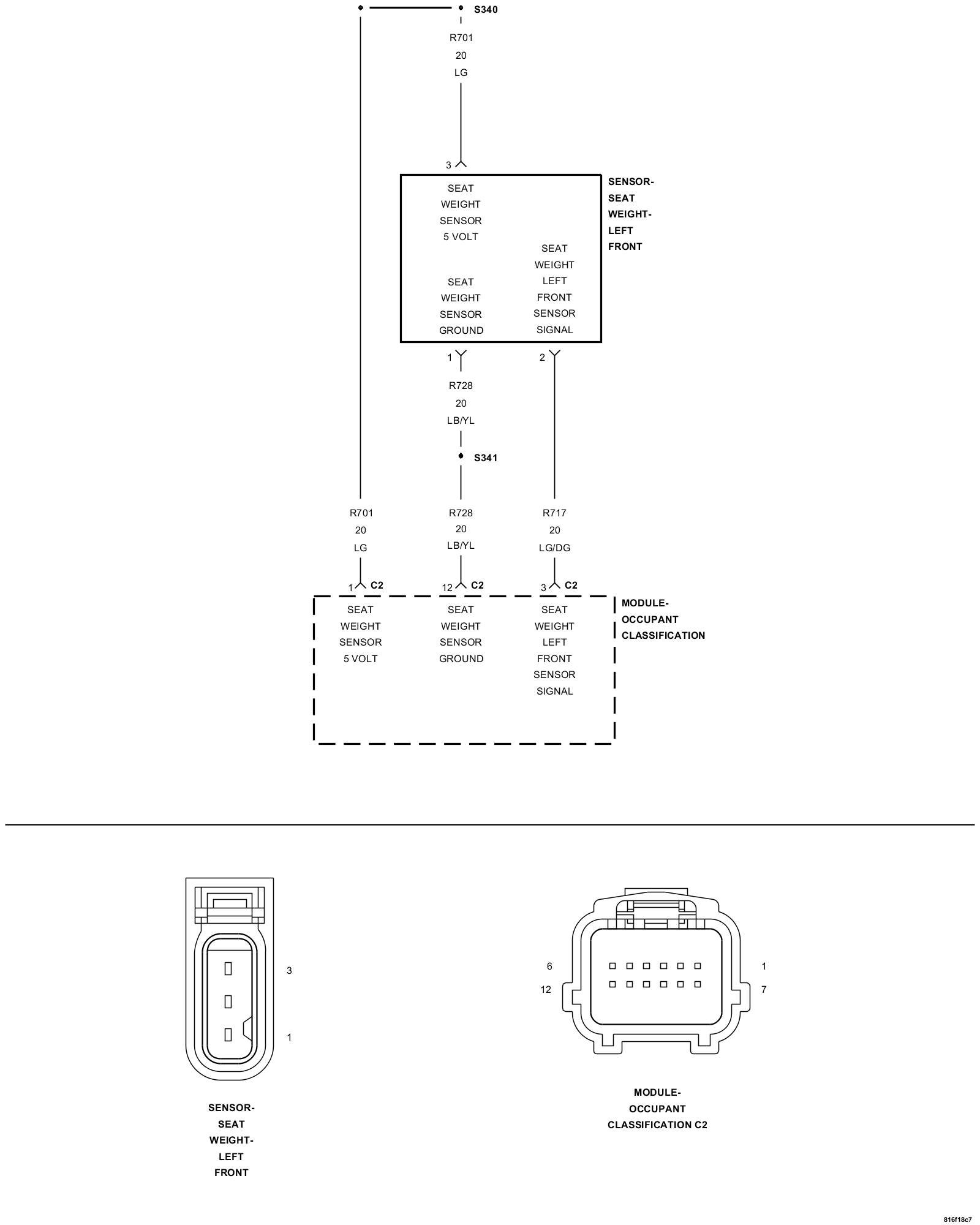
For a complete wiring diagram refer to the Wiring Information Electrical Diagrams.
- When Monitored:
While the CAN bus ignition status is in IGN_RUN, the module checks the sensor input ranges.
- Set Condition:
If the module detects that the sensor input is less than 3.4 ±.6% of the (R701) Seat Weight Sensor 5 Volt circuit voltage. This DTC will also set if the (R701) Seat Weight Sensor 5 Volt circuit is shorted to ground. However, this condition would prevent communication with the OCM and cause a Lost Communication With OCM DTC to set in other modules. Also, this DTC will remain active after the condition that set this fault is no longer present. This condition is referred to as latching the DTC for the ignition cycle. Cycling the ignition key will change the status from active to stored if the condition that set the fault is no longer present.
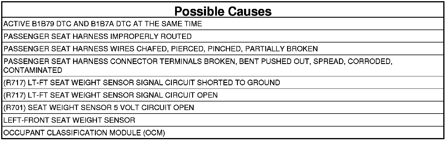
1. CHECK FOR ACTIVE INTERNAL FAULTS, IGNITION FAULTS, AND BATTERY FAULTS IN THE OCCUPANT CLASSIFICATION MODULE (OCM)
NOTE: Ensure that the battery is fully charged.
1. Turn the ignition on, then off, and then on again.
2. With the scan tool, read Occupant Classification Module (OCM) DTCs.
Does the scan tool display any active DTCs relating to internal faults, ignition faults, or battery faults?
Yes
- Diagnose and repair the DTCs. Testing and Inspection.
No
- Go To 2
2. VERIFY THAT DTC B1B79-PASSENGER SEAT WEIGHT SENSOR 3 - LEFT FRONT INPUT CIRCUIT LOW IS ACTIVE
1. With the scan tool, read OCM DTCs.
Does the scan tool display active: B1B79-PASSENGER SEAT WEIGHT SENSOR 3 - LEFT FRONT INPUT CIRCUIT LOW?
Yes
- Go To 3
No
- Go To 10
3. VERIFY THAT B1B7A-PASSENGER SEAT WEIGHT SENSOR 3 - LEFT FRONT INPUT CIRCUIT HIGH DTC AND B1B79-PASSENGER SEAT WEIGHT SENSOR 3 - LEFT FRONT INPUT CIRCUIT LOW DTC ARE ACTIVE AT THE SAME TIME
1. With the scan tool, read OCM DTCs.
Does the scan tool display active: B1B7A-PASSENGER SEAT WEIGHT SENSOR 3 - LEFT FRONT INPUT CIRCUIT HIGH AND B1B79-PASSENGER SEAT WEIGHT SENSOR 3 - LEFT FRONT INPUT CIRCUIT LOW AT THE SAME TIME?
Yes
- Perform B1B7A-PASSENGER SEAT WEIGHT SENSOR 3 - LEFT FRONT INPUT CIRCUIT HIGH diagnostic test. B1B7A.
No
- Go To 4
4. INSPECT PASSENGER SEAT HARNESS WIRES AND CONNECTORS
WARNING: Turn the ignition off, disconnect the 12-volt battery and wait two minutes before proceeding. Failure to follow these instructions may result in possible serious or fatal injury.
1. Using the wiring diagram/schematic as a guide, inspect the Passenger Seat Harness wiring and connectors. Look for chafed, pierced, pinched, or partially broken wires and broken, bent, pushed out, spread, corroded, or contaminated terminals.
Are any of these conditions present?
Yes
- NOTE: Do not attempt to repair the Seat Harness. Replace the Seat Harness if the condition inspecting or testing for is present in the Seat Harness.
- Replace the Passenger Seat Harness.
- Perform OCCUPANT CLASSIFICATION MODULE SYSTEM VERIFICATION TEST. Occupant Classification Module (OCM) System Verification Test.
- Perform AIRBAG SYSTEM VERIFICATION TEST. Airbag System Verification Test.
No
- Go To 5
5. VERIFY THAT PASSENGER SEAT HARNESS IS ROUTED CORRECTLY
1. Verify that the Passenger Seat Harness is routed correctly.
Is the Passenger Seat Harness routed correctly?
Yes
- Go To 6
No
- Reroute the Passenger Seat Harness as necessary.
- Perform OCCUPANT CLASSIFICATION MODULE SYSTEM VERIFICATION TEST. Occupant Classification Module (OCM) System Verification Test.
- Perform AIRBAG SYSTEM VERIFICATION TEST. Airbag System Verification Test.
6. CHECK VOLTAGE OF (R701) SEAT WEIGHT SENSOR 5 VOLT CIRCUIT
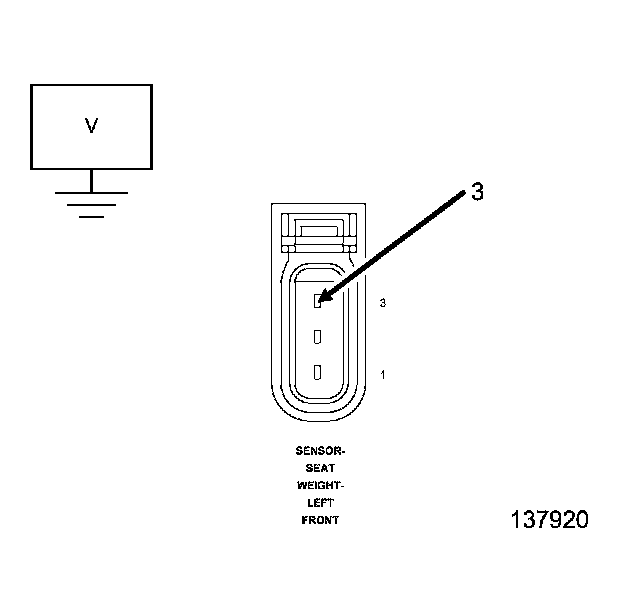
1. Disconnect the Left-Front Seat Weight Sensor connector.
WARNING: Turn the ignition on, then reconnect the 12-volt battery. Wait two minutes before proceeding. Failure to follow these instructions may result in possible serious or fatal injury.
2. Measure the voltage of the (R701) Seat Weight Sensor 5 Volt circuit.
Is the voltage above 4.8 volts?
Yes
- Go To 7
No
- Go To 9
7. CHECK (R717) LT-FT SEAT WEIGHT SENSOR SIGNAL CIRCUIT FOR A SHORT TO GROUND
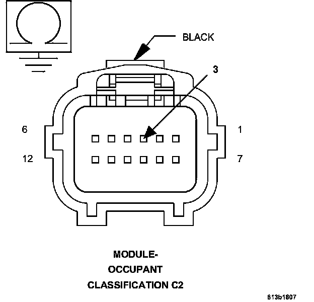
WARNING: Turn the ignition off, disconnect the 12-volt battery and wait two minutes before proceeding. Failure to follow these instructions may result in possible serious or fatal injury.
1. Disconnect the OCM C2 connector.
2. Measure the resistance of the (R717) LT-FT Seat Weight Sensor Signal circuit between ground and the OCM C2 connector.
Is the resistance below 5.0 ohms?
Yes
- NOTE: Do not attempt to repair the Seat Harness. Replace the Seat Harness if the condition inspecting or testing for is present in the Seat Harness.
- Replace the Passenger Seat Harness.
- Perform OCCUPANT CLASSIFICATION MODULE SYSTEM VERIFICATION TEST. Occupant Classification Module (OCM) System Verification Test.
- Perform AIRBAG SYSTEM VERIFICATION TEST. Airbag System Verification Test.
No
- Go To 8
8. CHECK (R717) LT-FT SEAT WEIGHT SENSOR SIGNAL CIRCUIT FOR AN OPEN
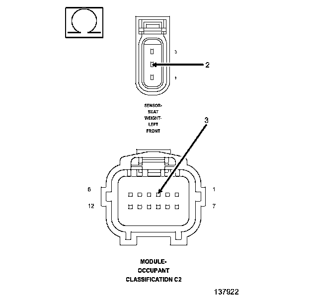
1. Measure the resistance of the (R717) LT-FT Seat Weight Sensor Signal circuit between the OCM C2 connector and the Left-Front Seat Weight Sensor connector.
Is the resistance below 5.0 ohms?
Yes
- Replace the Left-Front Seat Weight Sensor.
- Perform OCCUPANT CLASSIFICATION MODULE SYSTEM VERIFICATION TEST. Occupant Classification Module (OCM) System Verification Test.
- Perform AIRBAG SYSTEM VERIFICATION TEST. Airbag System Verification Test If DTC B1B79-PASSENGER SEAT WEIGHT SENSOR 3 - LEFT FRONT INPUT CIRCUIT LOW returns active, replace the OCM and perform the OCCUPANT CLASSIFICATION MODULE SYSTEM VERIFICATION TEST. Occupant Classification Module (OCM) System Verification Test.
No
- NOTE: Do not attempt to repair the Seat Harness. Replace the Seat Harness if any of these conditions exist.
- Replace the Passenger Seat Harness.
- Perform OCCUPANT CLASSIFICATION MODULE SYSTEM VERIFICATION TEST. Occupant Classification Module (OCM) System Verification Test.
- Perform AIRBAG SYSTEM VERIFICATION TEST. Airbag System Verification Test.
9. CHECK (701) SEAT WEIGHT SENSOR 5 VOLT CIRCUIT FOR AN OPEN
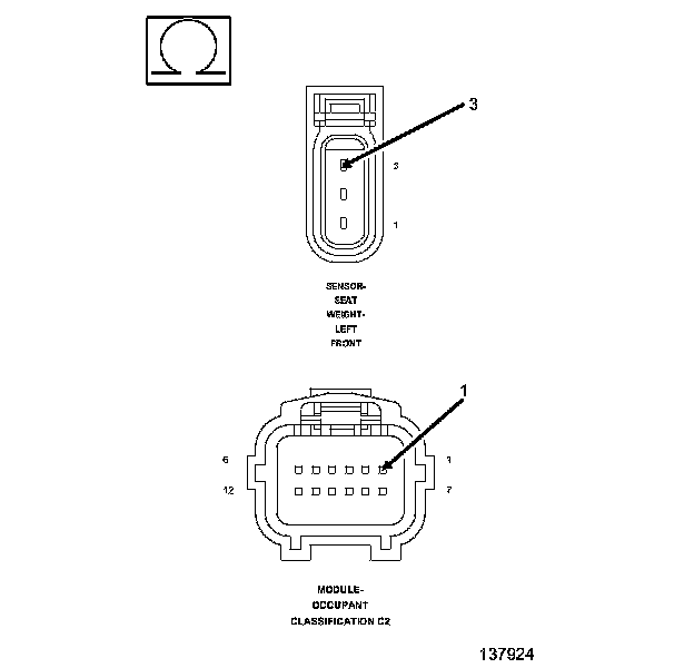
WARNING: Turn the ignition off, disconnect the 12-volt battery and wait two minutes before proceeding. Failure to follow these instructions may result in possible serious or fatal injury.
1. Disconnect the OCM C2 connector.
2. Measure the resistance of the (R701) Seat Weight Sensor 5 Volt circuit between the OCM C2 connector and the Left-Front Seat Weight Sensor connector.
Is the resistance below 5.0 ohms?
Yes
- Replace the OCM.
- Perform OCCUPANT CLASSIFICATION MODULE SYSTEM VERIFICATION TEST. Occupant Classification Module (OCM) System Verification Test.
- Perform AIRBAG SYSTEM VERIFICATION TEST. Airbag System Verification Test.
No
- NOTE: Do not attempt to repair the Seat Harness. Replace the Seat Harness if the condition inspecting or testing for is present in the Seat Harness.
- Replace the Passenger Seat Harness.
- Perform OCCUPANT CLASSIFICATION MODULE SYSTEM VERIFICATION TEST. Occupant Classification Module (OCM) System Verification Test.
- Perform AIRBAG SYSTEM VERIFICATION TEST. Airbag System Verification Test.
10. CHECKING STORED OR INTERMITTENT CODES
NOTE: Diagnose and repair all active codes before diagnosing stored codes.
1. With the scan tool, record and erase all Airbag System Module DTCs.
WARNING: Turn the ignition off disconnect the 12-volt battery and wait two minutes before proceeding. Failure to follow these instructions may result in possible serious or fatal injury.
2. Using the wiring diagram/schematic as a guide, inspect the related wiring and connectors for chafed, pierced, pinched, and partially broken wires, and for broken, bent, pushed out, corroded, and contaminated terminals. Repair as necessary.
3. Reconnect all disconnected components and harness connectors.
WARNING: Turn the ignition on, then reconnect the 12-volt battery and wait two minutes before proceeding. Failure to follow these instructions may result in possible serious or fatal injury.
4. With the scan tool, monitor for active codes while performing the following:
WARNING: Maintain a safe distance from all airbags while performing the following steps. Failure to follow these instructions may result in possible serious or fatal injury.
- Wiggle the wiring harness and connectors of the related airbag circuit.
- Continue the test until either a code becomes active or the problem area is isolated.
5. In the previous steps you have attempted to recreate the conditions responsible for setting the DTC in question/causing the intermittent condition.
Are any ACTIVE DTCs present?
Yes
- Select the appropriate diagnostic procedure. Testing and Inspection.
No
- No problem found at this time. Perform the Occupant Classification Module System Verification Test. Occupant Classification Module (OCM) System Verification Test Erase all codes before returning vehicle to customer. Occupant Classification Module (OCM) System Verification Test.