- If hub and bearing and dust shield needs to be installed on knuckle, perform following:
- Slide shield onto rear of hub and bearing.
- Slide hub and bearing into knuckle, lining up mounting holes in hub and bearing with those in shield and knuckle
- Install four bolts (3) fastening hub and bearing in place. Tighten mounting bolts to 68 N.m (50 ft. lbs.).
 Courtesy of CHRYSLER LLC
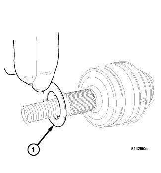
NOTE:
Before installing hub and bearing on end of axle half shaft, ensure isolation washer is present on end of half shaft. Inspect washer making sure it is not worn or damaged. Washer can be installed in either direction on shaft.
 Courtesy of CHRYSLER LLC
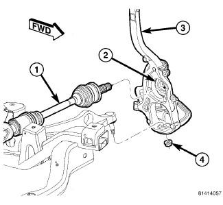
- Place knuckle (3) over lower ball joint stud and guide hub and bearing (2) onto axle half shaft (1).
- Start NEW nut (4) on lower ball joint stud. Do not tighten at this time.
 Courtesy of CHRYSLER LLC
CAUTION:
It is important to tighten nut as described in following step to avoid damaging ball stud joint.
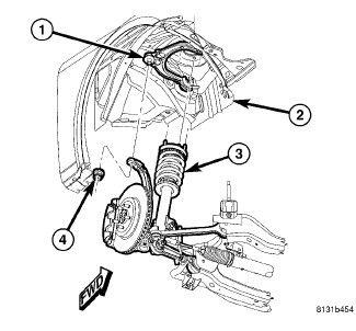
- Place upper ball joint stud (1) through hole in top of knuckle and install nut (4). Tighten nut by holding ball joint stud with a hex wrench while turning nut with a wrench. Tighten nut using crow foot wrench on torque wrench to 47 N.m + 90° turn (35 ft. lbs. + 90° turn).
Courtesy of CHRYSLER LLC
CAUTION:
It is important to tighten nut as described in following step to avoid damaging ball stud joint.
- Tighten lower ball joint nut (4) by holding ball joint stud with a hex wrench while turning nut with a wrench. Tighten nut using crow foot wrench on torque wrench to 68 N.m + 90° turn (50 ft. lbs. + 90° turn).
 Courtesy of CHRYSLER LLC
CAUTION:
It is important to tighten nut as described in following step to avoid damaging ball stud joint.
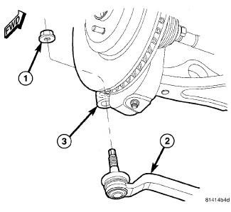
- Place outer tie rod stud through hole in knuckle (3) and install nut (1). Tighten nut by holding stud with a wrench while turning nut with another wrench. Tighten nut using crow foot wrench on torque wrench to 85 N.m (63 ft. lbs.).
- Install brake rotor, then disc brake caliper and adapter assembly. Refer to Brakes/Hydraulic/Mechanical/ROTOR, Brake - Installation
 Courtesy of CHRYSLER LLC
NOTE:
Always install a new hub nut. The original hub nut is one-time use only and should be discarded when removed.
- Install hub nut (1) on end of axle half shaft (2). While a helper applies brakes to keep hub from turning, tighten hub nut to 213 N.m (157 ft. lbs.).
 Courtesy of CHRYSLER LLC
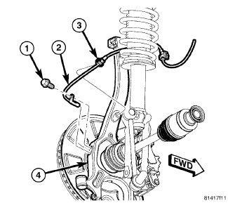
- Install wheel speed sensor (2) head into knuckle (4) and install mounting screw (1). Tighten screw to 11 N.m (95 in. lbs.).
- Attach wheel speed sensor cable routing clip (3) at knuckle (4).
 Courtesy of CHRYSLER LLC
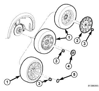
- Install tire and wheel assembly (1). Refer to Tires and Wheels - Installation
. Tighten wheel mounting nuts (3) to 150 N.m (110 ft. lbs.) (Police - 190 N.m (140 ft. lbs.)).
- Lower vehicle.
 Courtesy of CHRYSLER LLC
- Pump brake pedal several times to ensure vehicle has a firm brake pedal before moving vehicle.
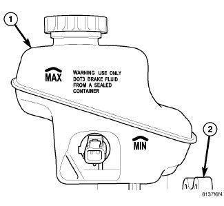
- Check and adjust brake fluid level in reservoir (1) as necessary.
- Perform wheel alignment. See Front Suspension/Wheel Alignment - Standard Procedure