- Raise and support vehicle. Refer to Vehicle Quick Reference/Hoisting - Standard Procedure
.
- Remove wheel mounting nuts (3), then tire and wheel assembly (1).
 Courtesy of CHRYSLER LLC
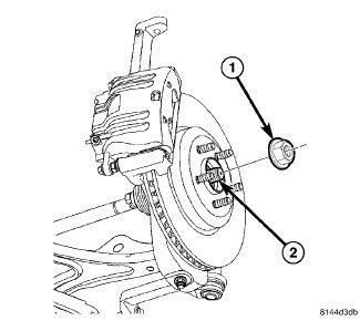
- While a helper applies brakes to keep hub from rotating, remove hub nut (1) from the axle half shaft (2).
- Remove belly pan. Refer to Body/Exterior/BELLY PAN - Removal
 Courtesy of CHRYSLER LLC
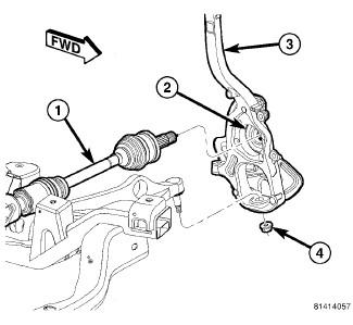
- Loosen nut (4) attaching lower control arm ball joint stud to knuckle (3). Back nut off until nut is even with end of stud. Keeping nut on at this location will help keep end of stud from distorting while using Puller in next step.
 Courtesy of CHRYSLER LLC
CAUTION:
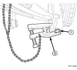
In following step, use care not to damage ball joint seal boot while sliding Puller, Special Tool 9360, into place past seal boot.
- Using Puller (2), Special Tool 9360, separate ball joint stud from knuckle.
- Remove tool.
- Remove nut (1) from end of ball joint stud.
 Courtesy of CHRYSLER LLC
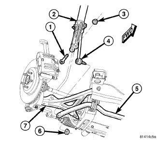
- Back off nut (3) from bolt (1) attaching shock clevis bracket (2) to lower control arm (7) until it is flush with end of bolt.
- Using a brass drift punch, tap the bolt out of the clevis bracket until bolt serrations clear bracket.
- Remove nut (3) and bolt (1) for clevis bracket and control arm.
 Courtesy of CHRYSLER LLC
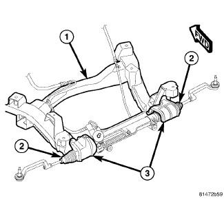
- Remove mounting screws, then heat shields (3) above both inner tie rod bellows (2).
 Courtesy of CHRYSLER LLC
CAUTION:
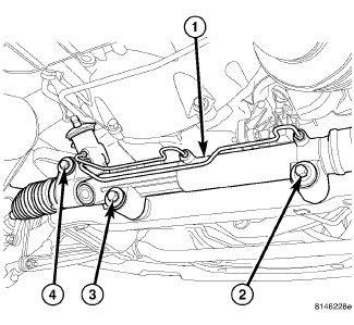
While steering gear bolts are removed, it important to avoid putting downward force on steering gear.
- Remove steering gear mounting bolts as listed:
- Left side arm - Remove bolts (3) and (4). Loosen, but do not remove, bolt (2). It is important leave bolt (2) installed to avoid dropping gear too far, putting excessive force on steering coupling.
- Right side arm - Remove bolts (2) and (3). Loosen, but do not remove, bolt (4). It is important to leave bolt (4) installed to avoid dropping gear too far, putting excessive force on steering coupling.
 Courtesy of CHRYSLER LLC
CAUTION:
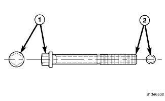
If the lower control arm bolt at the engine cradle has a lengthwise grooved shaft (2), it is a special wheel alignment adjustment bolt and the bolt head (1) must not be rotated in the vehicle or damage to the bolt and engine cradle will result. While holding the bolt in place with a wrench, remove the nut, then slide the bolt out of the bushing and cradle taking note of bolt positioning in engine cradle for reassembly purposes. The bolt needs to be installed in the same position as removed to make sure wheel camber and caster return to adjusted position.
 Courtesy of CHRYSLER LLC
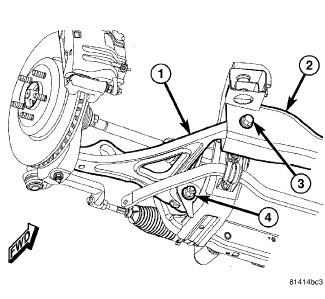
- Remove bolt (3) and nut securing forward end of lower control arm (1) to engine cradle (2). If bolt has a lengthwise grooved shaft (see above CAUTION), remove bolt and nut by holding bolt stationary with a wrench, removing nut, then sliding bolt out of bushing and cradle while taking note of bolt positioning in engine cradle for reassembly purposes.
- Remove bolt and nut (4) securing rearward end of lower control arm (1) to engine cradle (2). If bolt has a lengthwise grooved shaft (see above CAUTION), remove bolt and nut by holding bolt stationary with a wrench, removing nut, then sliding bolt out of bushing and cradle while taking note of bolt positioning in engine cradle for reassembly purposes.
- Slide lower control arm (1) from engine cradle (2) and knuckle, and remove from vehicle.