- Disconnect and isolate battery negative cable (2) from battery post.
- Raise and support vehicle. Refer to Vehicle Quick Reference/Hoisting - Standard Procedure
 Courtesy of CHRYSLER LLC
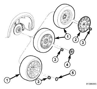
- On each side of vehicle rear, remove wheel mounting nuts (3), then tire and wheel assembly (1).
 Courtesy of CHRYSLER LLC
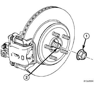
- On each side of vehicle rear, while a helper applies brakes to keep hub from rotating, remove hub nut (1) from half shaft (2).
 Courtesy of CHRYSLER LLC
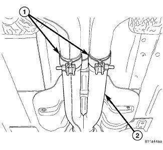
- Remove rear exhaust system (2) (dual-outlet exhaust shown in Fig 4).
- Remove rear axle differential. Refer to Differential and Driveline/Rear Axle - 200MM - Removal
- Slide each axle half shaft from hub and bearing and remove from vehicle.
 Courtesy of CHRYSLER LLC
NOTE:
Due to short travel and low spring tension, it is not necessary to lock-out parking brake lever to service parking brake components.
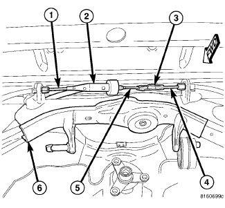
- Disconnect front parking brake cable (5) at connector (3) to right rear parking brake cable (4) above axle differential.
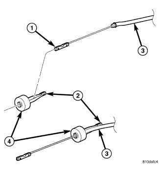 Courtesy of CHRYSLER LLC
- Remove front parking brake cable (3) from equalizer (2).
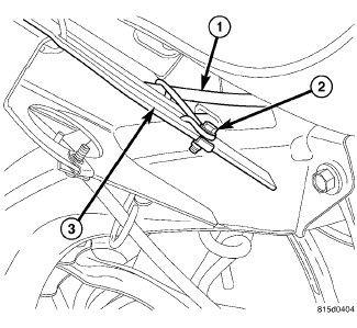 Courtesy of CHRYSLER LLC
- Remove screw (2) fastening front parking brake cable (1) routing bracket to rear crossmember front flange (3).
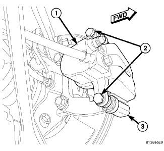 Courtesy of CHRYSLER LLC
- If equipped with standard or premium disc brakes, on each rear disc brake:
- While holding guide pins from turning, remove disc brake caliper guide pin bolts (2).
- Remove brake caliper (1) from brake adapter (3) and pads.
- Guide brake caliper up through suspension, following brake hose path. Support caliper above rear suspension using with bungee cord or wire to keep caliper from overextending brake hose when crossmember is lowered.
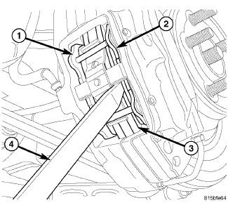 Courtesy of CHRYSLER LLC
CAUTION:
When pushing pistons back into caliper bores, use only a trim stick as shown in Fig 9 or other suitable soft tool. Never use a screwdriver or other metal pry bar due to potential damage to braking surface of rotor, caliper, pistons or dust boots.
- If equipped with SRT8 disc brakes, on each rear disc brake, place trim stick (4) between brake pad (2) and outer edge of rotor (3).
- If equipped with SRT8 disc brakes, on each rear disc brake, using trim stick, slowly apply pressure against brake pad (2) until both pistons (on that side of caliper) are completely bottomed in bores of caliper half.
NOTE:
Repeat above procedure to opposite brake pad (1) and pistons as necessary.
 Courtesy of CHRYSLER LLC
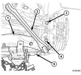
- If equipped with SRT8 disc brakes, on each rear disc brake, support spring link (1) using a transmission jack (5) or other appropriate jack. Raise spring link just enough to access brake caliper lower mounting bolt (4) from above compression link (2).
 Courtesy of CHRYSLER LLC
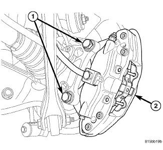
- If equipped with SRT8 disc brakes, on each rear disc brake, remove the lower and upper caliper mounting bolts (1).
- If equipped with SRT8 disc brakes, on each rear disc brake, remove brake caliper (2) with pads from knuckle and brake rotor. Hang assembly out of way using wire or a bungee cord. Use care not to overextend brake hose when doing this.
- If equipped with SRT8 disc brakes, remove jack from under spring link.
 Courtesy of CHRYSLER LLC
NOTE:
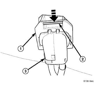
To remove wheel speed sensor connector from body wiring harness connector, move retaining clip (2) and pull sensor connector outward.
 Courtesy of CHRYSLER LLC
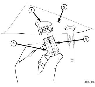
- Remove wheel speed sensor connectors (3 and 4) from body wiring harness connector (1) located in luggage compartment floor pan (2).
 Courtesy of CHRYSLER LLC
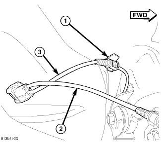
- Unclip left wheel speed sensor cable (3) from routing clip (1) near body connector.
 Courtesy of CHRYSLER LLC
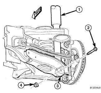
- On each side of vehicle, remove shock absorber (1) lower mounting bolt (2) and nut (4).
 Courtesy of CHRYSLER LLC
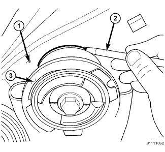
| 1 - BODY |
| 2 - MARKER (OR CRAYON) |
| 3 - CROSSMEMBER BUSHING FLANGE |
- Carefully mark location of rear crossmember on body at all four mount (bushing) locations using a marker or crayon. Do not use a scratch awl to mark location.
- Position an extra pair of jack stands under and support forward end of engine cradle to help stabilize vehicle during rear suspension removal/installation.
 Courtesy of CHRYSLER LLC
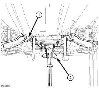
- Position under-hoist utility jack or transmission jack (2) under center of rear crossmember (1). Raise jack head to contact crossmember and secure in place.
 Courtesy of CHRYSLER LLC
WARNING:
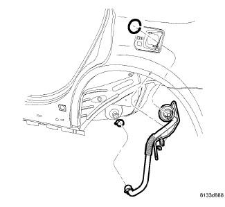
Before opening fuel system, review all Warnings and Cautions.
- Remove fuel filler tube. Refer to Fuel System/Fuel Delivery/TUBE, Fuel Tank Filler - Removal
 Courtesy of CHRYSLER LLC
NOTE:
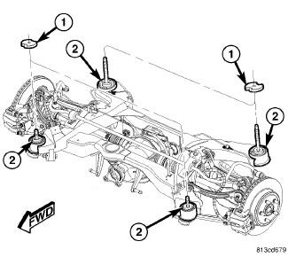
If equipped with AWD, when removing crossmember mounting bolts in following step, be sure to not to misplace spacers (1) between crossmember mounts (2) and body.
 Courtesy of CHRYSLER LLC
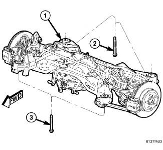
- Remove both front (3) and both rear (2) mounting bolts fastening crossmember (1) in place.
- Slowly
lower crossmember using jack until crossmember is at a comfortable working level.
 Courtesy of CHRYSLER LLC
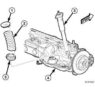
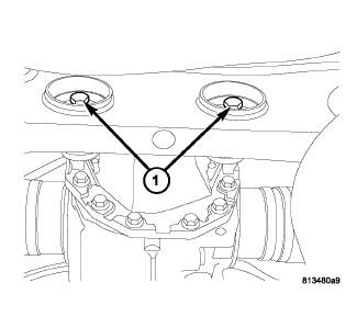
- Remove coil springs and isolators (1, 2 and 5) from spring links.
 Courtesy of CHRYSLER LLC
- Remove bolt (1) from bushing prior to removal.
 Courtesy of CHRYSLER LLC
NOTE:
Prior to using Special Tool 9520, lubricate Bolt (1) threads to provide ease of use and promote tool longevity.
NOTE:
When installing Thrust Bearing (6), be sure to place hardened side toward Bolt head.
- Assemble tools (See following list) over bushing as shown in Fig 23.
- (1) Bolt
- (2) Nut
- (3) Washer
- (4) Receiver 9520-4
- (5) Remover 9520-3
- (6) Thrust Bearing
- While holding Nut (2) from rotating, using hand tools
, tighten Bolt (1) until Remover (5) comes in contact with bushing and Receiver (4) sets squarely against crossmember.
- Continue to tighten Bolt (1), pressing bushing out of crossmember.
- Remove tools with bushing.