Ignition Switch
- Remove ignition switch. See IGNITION SWITCH & LOCK CYLINDER under REMOVAL & INSTALLATION. Check continuity between ignition switch terminals No. 3 and 5 with ignition switch in START and RUN positions. See Fig 1. If continuity exists, go to next step. If continuity does not exist, replace ignition switch.
- Check continuity between ignition switch terminals No. 4 and 5 with ignition switch in START position. If continuity exists, go to next step. If continuity does not exist, replace ignition switch.
- Ignition switch sends multiplexed commands to Body Control Module (BCM). Use scan tool to diagnose affected system(s). For diagnosis and repair, see BODY CONTROL MODULES - CARAVAN, TOWN & COUNTRY, & VOYAGER article. For ignition switch circuit function, see IGNITION SWITCH CIRCUIT FUNCTIONS table.
IGNITION SWITCH CIRCUIT FUNCTIONS
| Terminal No. (Wire Color) |
Circuit Function |
| 1 (Violet/Orange) |
Ignition Sense Return |
| 2 (Violet/Brown) |
Ignition Sense |
| 3 (Pink/White) |
Fused Ignition Switch Output (START/RUN) |
| 4 (Yellow) |
Ignition Switch Output (START) |
| 5 (Light Blue/Red) |
Fused Battery Voltage |
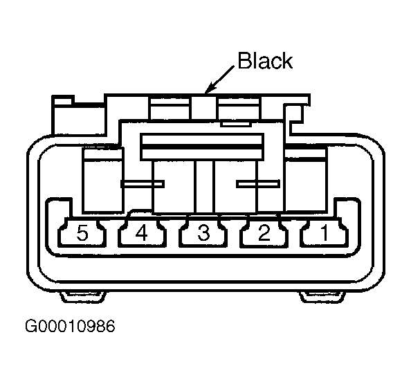 Courtesy of DAIMLERCHRYSLER CORPORATION