Timing Belt: Installation
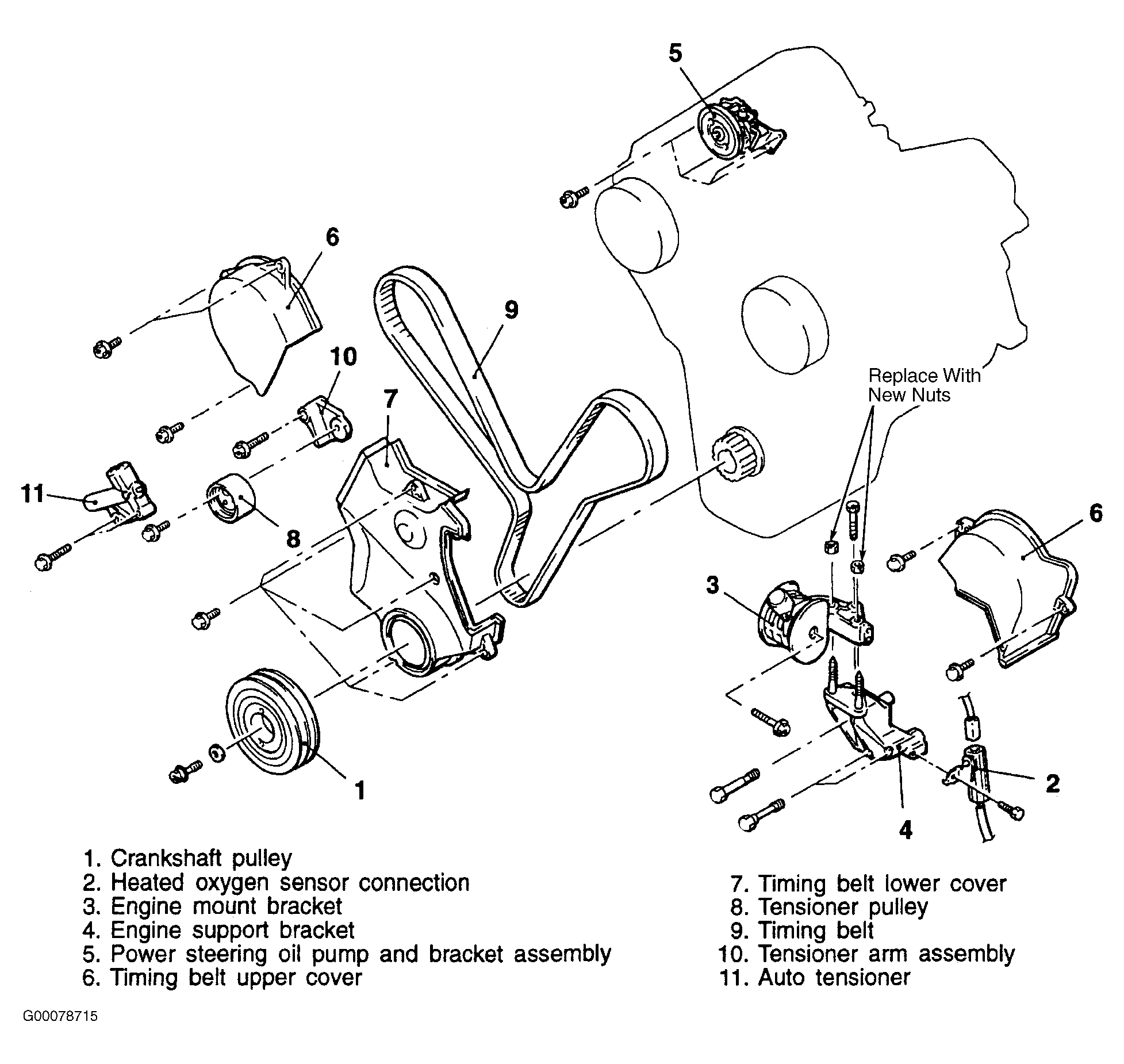
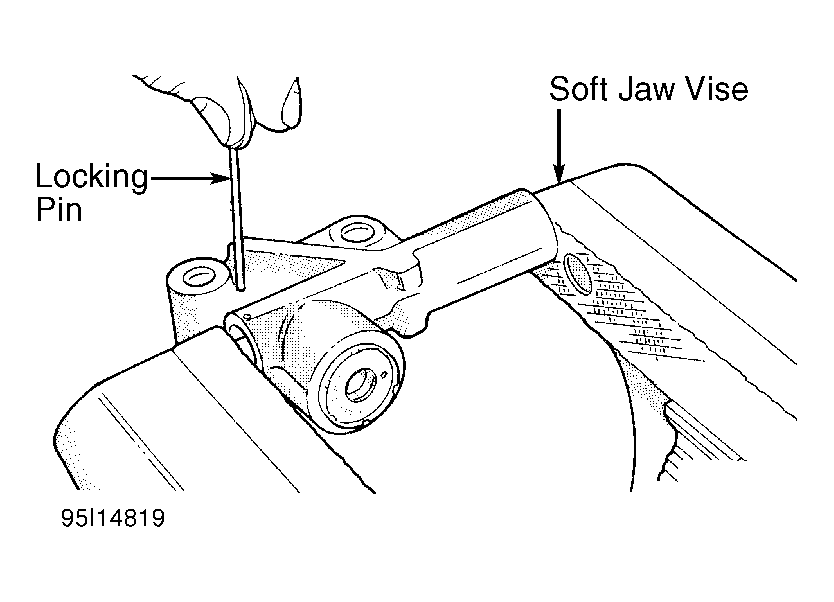
- Place tensioner into vise at a right angle to the pressing surface of the vise and slowly compress plunger. When plunger is compressed into tensioner body, install a stiff, "L" shaped, .06" (1.5 mm) pin through body and plunger to retain plunger until tensioner is installed. Index tensioner in vise same direction as installed. This will ensure proper pin orientation when tensioner is installed in engine. See Fig 3. Install tensioner arm assembly and tighten bolts to 33 ft. lbs. (45 N.m). Install tensioner to tensioner arm assembly and tighten bolts to 17 ft. lbs. (23 N.m). Install tensioner pulley.
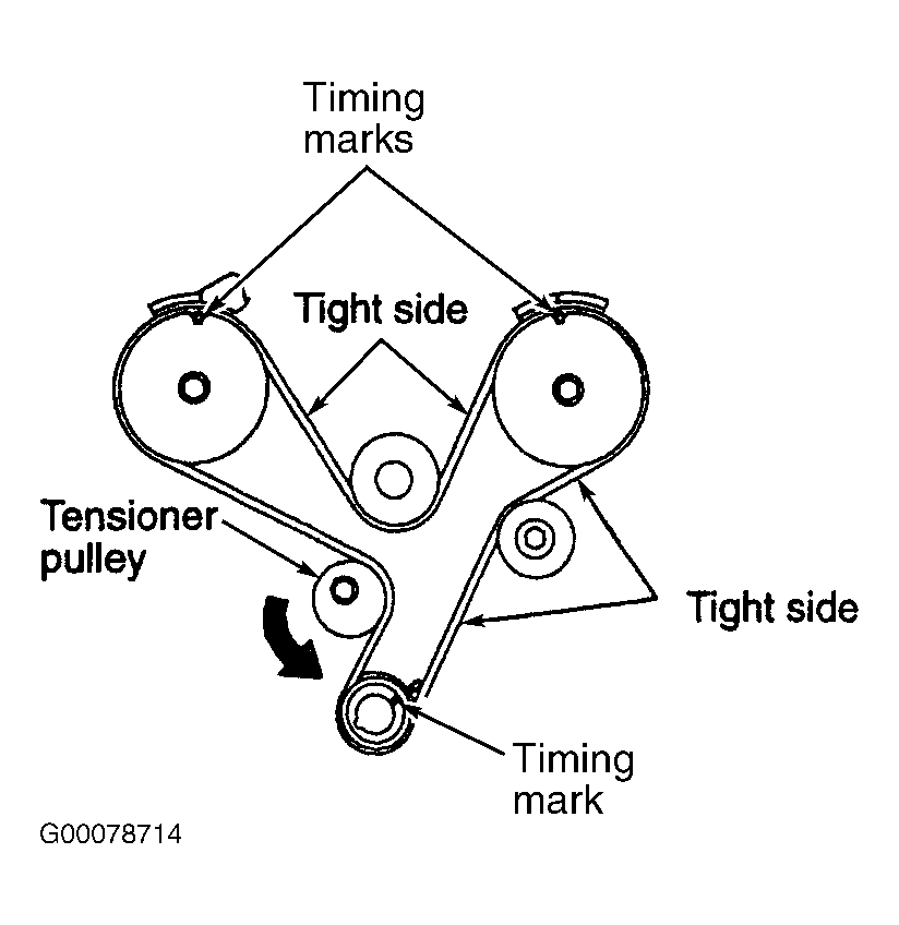
- Set crankshaft to TDC by aligning mark on sprocket with mark on oil pump housing. See Fig 4. Set camshaft sprockets by aligning timing marks on sprockets with marks on rocker covers.
- Install timing belt on crankshaft and install a binder clip to keep belt in position. Install belt over idler pulley and then around left (front bank) camshaft sprocket. Install another binder clip on left sprocket and belt. Keeping belt taught, install belt underneath water pump pulley and then around right camshaft sprocket and install a binder clip on right sprocket and belt. Continue routing belt over tensioner pulley and around crankshaft sprocket.
- Apply rotating force to right camshaft sprocket (closest to firewall) in a counterclockwise direction to tension belt. Ensure all timing marks are aligned. Rotate tensioner pulley in direction of arrow, to remove any belt slack, and temporarily tighten tensioner pulley bolt.
- Rotate crankshaft 1/4 turn counterclockwise and back (clockwise) to timing mark. Loosen tensioner pulley bolt.
- Using Tensioner Wrench (MD998767) and a torque wrench, apply 39 INCH lbs. (4.4 N.m) to tensioner and tighten tensioner pulley bolt to 35 ft. lbs. (47 N.m). Ensure that when tightening bolt, tensioner pulley shaft does not rotate with bolt.
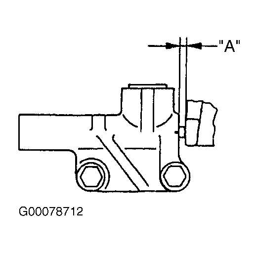
- Pull tensioner plunger locking pin. Pin should be easily removed. Rotate crankshaft 2 revolutions clockwise, and check alignment of timing marks. Allow belt to rest at least 5 minutes. Install tensioner pin into assembly. Pin should slide in and out with no resistance. If pin does not slide in and out, it is satisfactory if tensioner rod projection is .15-.18" (3.8-4.5 mm). See Fig 5. If pin does not slide freely and tensioner rod projection is not as specified, repeat steps 5) - 7)
.
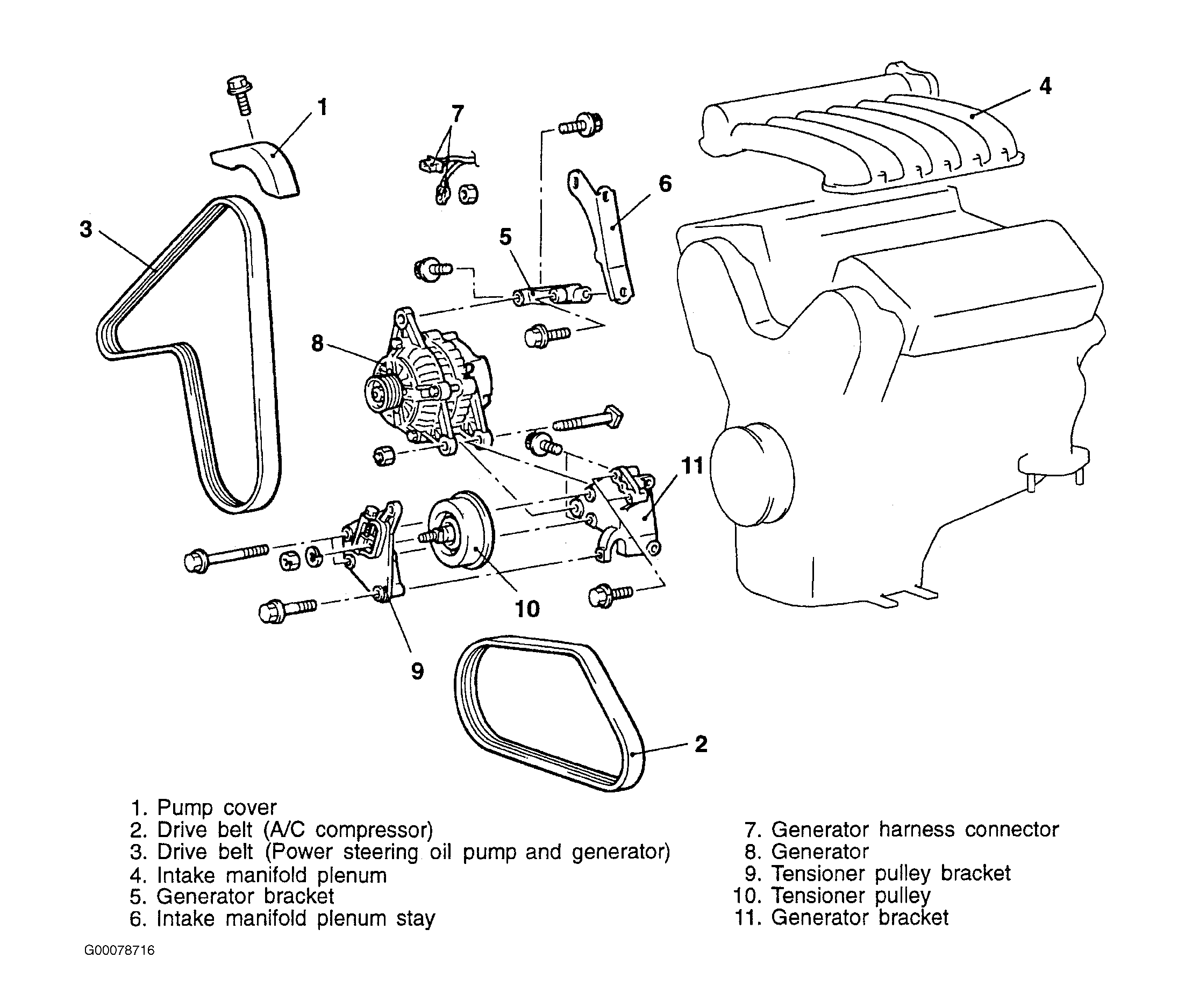
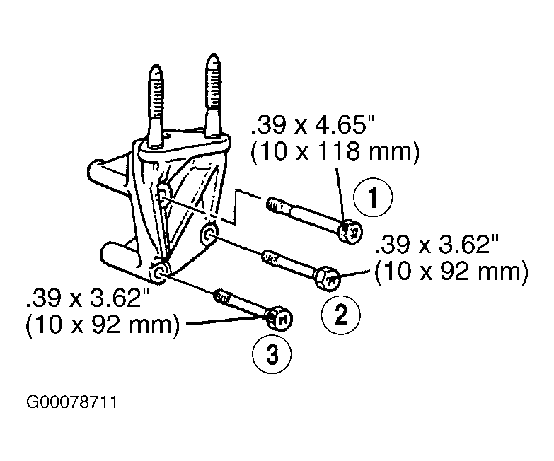
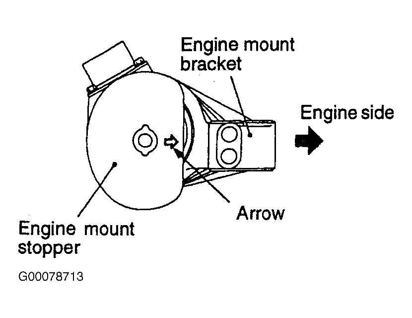
- To complete installation, reverse removal procedure. Using crankshaft pulley holder, install crankshaft pulley. Tighten crankshaft damper bolt to 13 ft. lbs. (18 N.m). Install engine support bracket bolts in sequence. See Fig 6. When installing reamer bolt 1, tighten it slowly, while lubricating reamer area. Install engine mount bracket so that arrow on engine mount stopper is pointing to engine. See Fig 7. Install NEW engine mount bracket nuts. Adjust accessory drive belt tension. See appropriate SPECIFICATIONS & ELECTRIC COOLING FANS article in ENGINE COOLING. Tighten all fasteners to specification. See TORQUE SPECIFICATIONS .
 Courtesy of CHRYSLER CORP.
 Courtesy of CHRYSLER CORP.
 Courtesy of CHRYSLER CORP.
 Courtesy of CHRYSLER CORP.
 Courtesy of CHRYSLER CORP.
 Courtesy of CHRYSLER CORP.
 Courtesy of CHRYSLER CORP.