Tachometer Circuit Test
- Remove cluster, radio and rear window defogger bezels and mask/lens assembly. Check for battery voltage at cavity "A" of instrument cluster Black connector. See Fig 1
.
- With ignition switch in ON position, check for battery voltage at cavity "C" of Black connector. See Fig 1
.
- Check cavity "H" of Black connector for continuity to ground. Check for tachometer signal from powertrain control module by connecting an AC digital voltmeter to cavity "B" of instrument cluster black connector and ground. Voltage should be at least 1.0 volt with engine running.
- If voltage is within specification, go to step 6). If voltage is less than 1.0 volt at cavity "B", check for continuity between cavity "B" and pin No. 43 of powertrain control module connector. See Fig 2
.
- If continuity exists between cavity "B" and pin No. 43, replace powertrain control module. If there is no continuity between cavity "B" and pin No. 43, check connectors for damaged pins, terminal push-outs or defective wire.
- If all tests are okay, replace tachometer drive module. If tachometer continues to be inoperative, replace tachometer assembly.
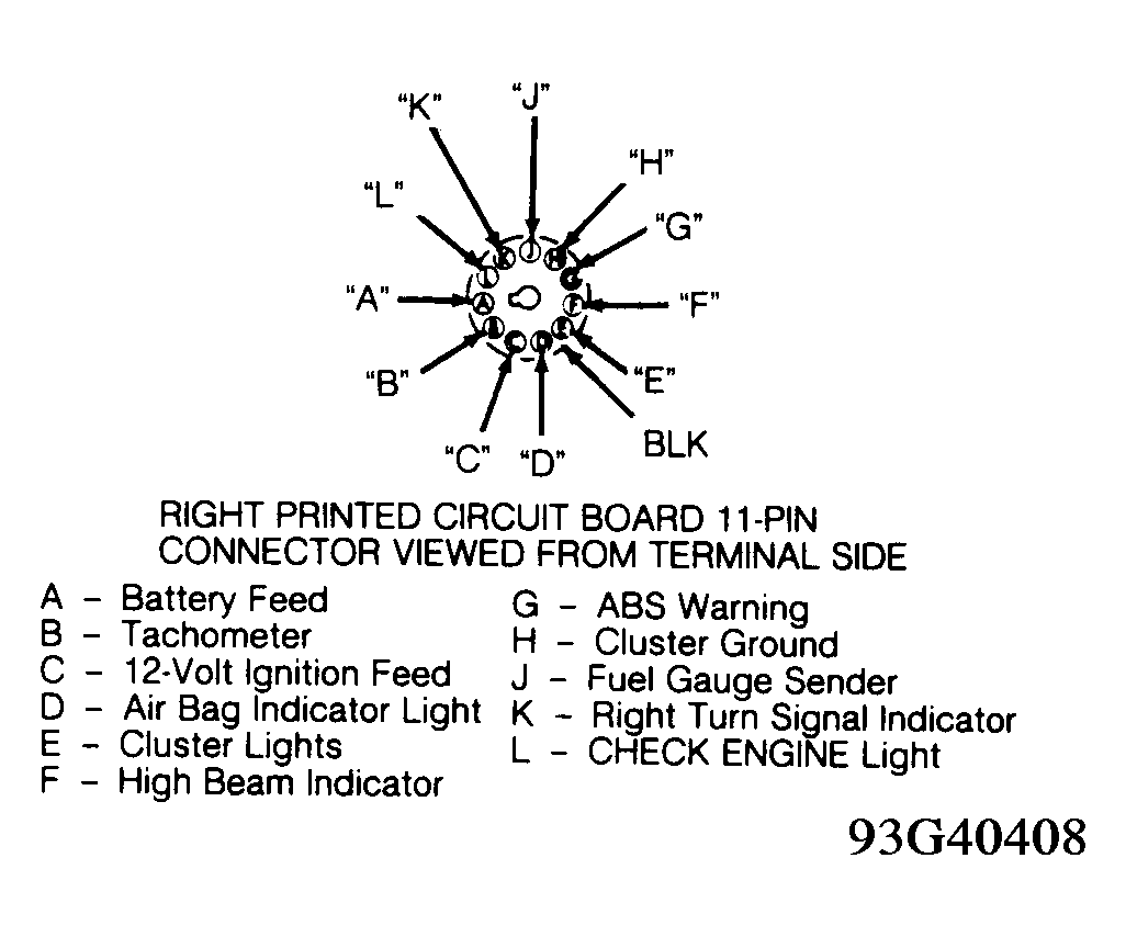 Courtesy of CHRYSLER CORP.
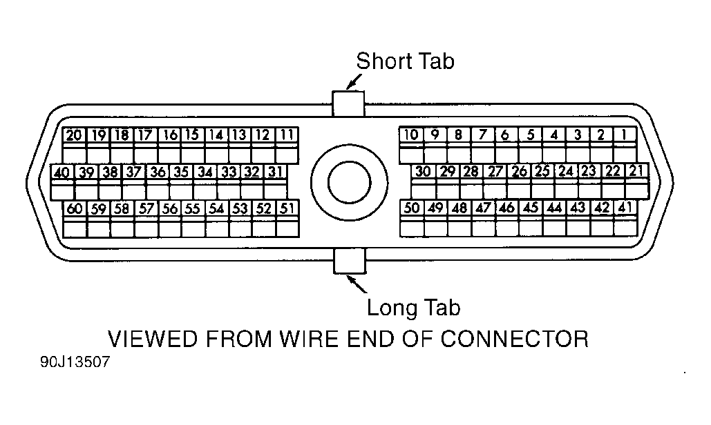 Courtesy of CHRYSLER CORP.