- Mount the engine (1) onto the engine stand (2). See Engine Removal and Installation (1 Of 3) ENGINE REMOVAL AND INSTALLATION (2 OF 3)
, or ENGINE REMOVAL AND INSTALLATION (3 OF 3)
 Courtesy of GENERAL MOTORS COMPANY Courtesy of GENERAL MOTORS COMPANY
|
- Remove EN-36857 Engine Lift Bracket (1) and EN-52059 Engine Support Fixture Adapter Bolt - M10 (2) from the cylinder head.
 Courtesy of GENERAL MOTORS COMPANY Courtesy of GENERAL MOTORS COMPANY
|
- Remove EN-36857 Engine Lift Bracket (1) and EN-52059 Engine Support Fixture Adapter Bolt - M10 (2) from the cylinder head.
 Courtesy of GENERAL MOTORS COMPANY Courtesy of GENERAL MOTORS COMPANY
|
- EN-42386-A Flywheel Holding Tool (1) - Install
- Install 1 M10-1.5 x 120 mm (3) bolt and 1 M10-1.5 x 45 mm bolt (2).
- Tighten the 2 bolts (2, 3) to 50 N.m (37 lb ft).
 Courtesy of GENERAL MOTORS COMPANY Courtesy of GENERAL MOTORS COMPANY
|
- Automatic Transmission Flex Plate Bolt (1) - Remove and DISCARD [8x]
 Courtesy of GENERAL MOTORS COMPANY Courtesy of GENERAL MOTORS COMPANY
|
- Automatic Transmission Flex Plate (1) - Remove
- Remove the M10-1.5 x 120 mm bolt (3) and the M10-1.5 x 45 mm bolt (2).
- EN-42386-A Flywheel Holding Tool (1) - Remove
 Courtesy of GENERAL MOTORS COMPANY Courtesy of GENERAL MOTORS COMPANY
|
- Engine Mount Engine Side Bolt - Left Side (1) - Remove [4x]
- Engine Mount - Left Side (2) - Remove
 Courtesy of GENERAL MOTORS COMPANY Courtesy of GENERAL MOTORS COMPANY
|
- Engine Mount Engine Side Bolt - Right Side (1) - Remove [4x]
- Engine Mount - Right Side (2) - Remove
 Courtesy of GENERAL MOTORS COMPANY Courtesy of GENERAL MOTORS COMPANY
|
- Rotate the oil filler tube (1) counterclockwise and remove from the valve rocker arm cover.
 Courtesy of GENERAL MOTORS COMPANY Courtesy of GENERAL MOTORS COMPANY
|
- Inspect the oil filler tube seal (2) on the oil filler tube (1) and replace as necessary.
 Courtesy of GENERAL MOTORS COMPANY Courtesy of GENERAL MOTORS COMPANY
|
- Belt Idler Pulley Bracket Bolt (1) - Remove [3x]
- Remove the belt idler pulley and belt idler pulley bracket (2) as an assembly.
 Courtesy of GENERAL MOTORS COMPANY Courtesy of GENERAL MOTORS COMPANY
|
- Grasp the left side valve rocker arm cover insulator (3) and lift up disengaging the 3 upper intake manifold sight shield grommets (2) from the 3 valve rocker arm cover insulator retainers (1).
- Valve Rocker Arm Cover Insulator - Left Side (3) - Remove
 Courtesy of GENERAL MOTORS COMPANY Courtesy of GENERAL MOTORS COMPANY
|
- Grasp the right side valve rocker arm cover insulator (3) and lift up disengaging the 3 upper intake manifold sight shield grommets (1) from the 3 valve rocker arm cover insulator retainers (2).
- Valve Rocker Arm Cover Insulator - Right Side (3) - Remove
 Courtesy of GENERAL MOTORS COMPANY Courtesy of GENERAL MOTORS COMPANY
|
NOTE:
Pull only on the spark plug wire boot to remove the wire.
NOTE:
Note: Inspect the spark plug wire for damage and replace if necessary.
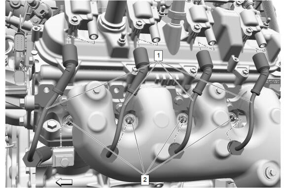
- Twist the 4 spark plug wire boots a 1/2 turn and remove the 4 spark plug wires (1) from the 4 gas engine ignition spark plugs (2).
 Courtesy of GENERAL MOTORS COMPANY Courtesy of GENERAL MOTORS COMPANY
|
NOTE:
Pull only on the spark plug wire boot to remove the wire.
NOTE:
Note: Inspect the spark plug wire for damage and replace if necessary.
- Twist the 4 spark plug wire boots a 1/2 turn and remove the 4 spark plug wires (1) from the 4 ignition coils (2).
 Courtesy of GENERAL MOTORS COMPANY Courtesy of GENERAL MOTORS COMPANY
|
- Disconnect the 4 ignition coil electrical connectors.
- Ignition Coil Bolt (1) - Remove [8x]
- Ignition Coil - Left Side (2) - Remove [4x]
 Courtesy of GENERAL MOTORS COMPANY Courtesy of GENERAL MOTORS COMPANY
|
- Twist the 4 spark plug wire boots a 1/2 turn and remove the 4 spark plug wires (1) from the 4 gas engine ignition spark plugs (2).
 Courtesy of GENERAL MOTORS COMPANY Courtesy of GENERAL MOTORS COMPANY
|
- Twist the 4 spark plug wire boots a 1/2 turn and remove the 4 spark plug wires (1) from the 4 ignition coils (2).
 Courtesy of GENERAL MOTORS COMPANY Courtesy of GENERAL MOTORS COMPANY
|
- Disconnect the 4 ignition coil electrical connectors.
- Ignition Coil Bolt (1) - Remove [8x]
- Ignition Coil - Right Side (2) - Remove [4x]
 Courtesy of GENERAL MOTORS COMPANY Courtesy of GENERAL MOTORS COMPANY
|
- Exhaust Manifold Heat Shield Bolt (1) - Remove [3x]
- Exhaust Manifold Heat Shield - Left Side (2) - Remove
 Courtesy of GENERAL MOTORS COMPANY Courtesy of GENERAL MOTORS COMPANY
|
- Exhaust Manifold Bolt (2) - Remove and DISCARD [5x]
- Exhaust Manifold - Left Side (3) - Remove
- Exhaust Manifold Gasket (1) - Remove and DISCARD
 Courtesy of GENERAL MOTORS COMPANY Courtesy of GENERAL MOTORS COMPANY
|
- Oil Level Indicator Tube Bolt (1) - Remove
 Courtesy of GENERAL MOTORS COMPANY Courtesy of GENERAL MOTORS COMPANY
|
- Remove the oil level indicator, oil level indicator tube and oil level indicator seal as an assembly (1)
- Oil Level Indicator Seal (2) - Remove and DISCARD
 Courtesy of GENERAL MOTORS COMPANY Courtesy of GENERAL MOTORS COMPANY
|
- Exhaust Manifold Heat Shield Bolt (1) - Remove [3x]
- Exhaust Manifold Heat Shield - Right Side (2) - Remove
 Courtesy of GENERAL MOTORS COMPANY Courtesy of GENERAL MOTORS COMPANY
|
- Exhaust Manifold Bolt (2) - Remove and DISCARD [5x]
- Exhaust Manifold - Right Side (3) - Remove
- Exhaust Manifold Gasket (1) - Remove and DISCARD
 Courtesy of GENERAL MOTORS COMPANY Courtesy of GENERAL MOTORS COMPANY
|
CAUTION:
Fuel feed intermediate pipes will be delivered with shipping caps that are meant to protect the mating joint threads. Do NOT remove shipping caps until the pipe is to be installed and joints are to be secured. Failure to do so could result in damage to the mating threads.
NOTE:
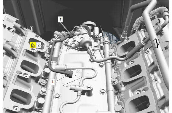
Do NOT reuse the fuel feed intermediate pipe (2). If the 2 fuel feed intermediate pipe nuts (1) are loosened or the fuel feed intermediate pipes are removed, the fuel feed intermediate pipes MUST be replaced.
- Fuel Feed Intermediate Pipe Nut (1) @ Fuel Feed Intermediate Pipe (2) - Loosen until disengaged [2x]
- Fuel Feed Intermediate Pipe (2) - Remove and DISCARD
 Courtesy of GENERAL MOTORS COMPANY Courtesy of GENERAL MOTORS COMPANY
|
NOTE:
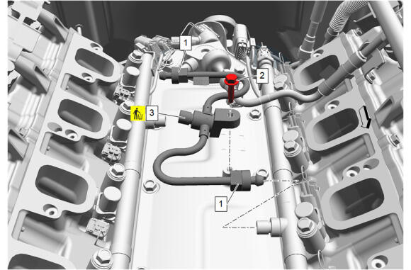
Note: Do NOT reuse the fuel feed intermediate pipe (3). If the 2 fuel feed intermediate pipe nuts (1) are loosened or the fuel feed intermediate pipes are removed, the fuel feed intermediate pipes MUST be replaced.
- Fuel Feed Intermediate Pipe Nut (1) - Loosen until disengaged [2x]
- Fuel Feed Pipe Bolt (2) - Remove
- Fuel Feed Intermediate Pipe (3) - Remove and DISCARD
- Disconnect and reposition the fuel pump and fuel injector wiring harness as necessary.
 Courtesy of GENERAL MOTORS COMPANY Courtesy of GENERAL MOTORS COMPANY
|
CAUTION:
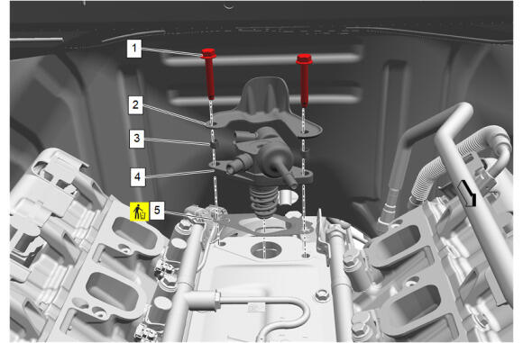
Alternately loosen the fuel pump bolts one turn at a time until the pump is fully disengaged from fuel pump lifter follower. Trying to remove the pump bolts without even side-to-side loosening may result in pump plunger damage
- Fuel Pump Bolt (1) - Remove [2x]
- Fuel Pump Cover (2) - Remove
- Fuel Pump Bolt Retainer (3) - Remove [2x]
- Fuel Pump (4) - Remove
- Fuel Pump Bracket Gasket (5) - Remove and DISCARD
- Clean the cylinder head around the fuel injectors on bank 1 of any dirt or buildup.
 Courtesy of GENERAL MOTORS COMPANY Courtesy of GENERAL MOTORS COMPANY
|
NOTE:
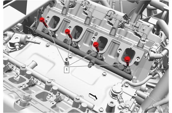
The 4 bank 1 fuel injection fuel rail bolts (1) are retained in the bank 1 fuel injection fuel rail and may be difficult to remove.
- Remove the 4 bank 1 fuel injection fuel rail bolts (1).
 Courtesy of GENERAL MOTORS COMPANY Courtesy of GENERAL MOTORS COMPANY
|
NOTE:
- In some cases, the fuel injectors may be difficult to remove because of heavy carbon build-up or other factors. If the fuel injectors are difficult to remove, apply solvent to the base of the fuel injector bores, and allow adequate soaking time, to loosen the fuel injectors.
- The bank 1 fuel injection fuel rail and fuel injectors are removed as an assembly.
- To prevent material from entering the combustions chambers make sure the area around each fuel injector is clean and free of debris before the fuel injectors are removed from the fuel injector bores.
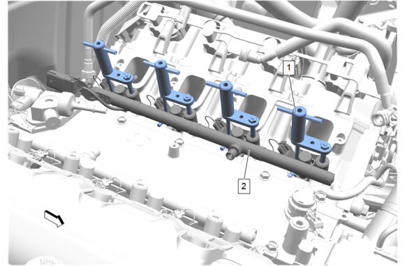
- Install 2 sets of EN-49248 Injector Rail Assembly Remover (1) on bank 1.
- Install one EN-49248 Injector Rail Assembly Remover (1) in each of the 4 bank 1 fuel injection fuel rail bolt bores.
- Turn each EN-49248 Injector Rail Assembly Remover (1) an even amount to pull the fuel injection fuel rail bank 1 (2) and fuel injectors out evenly.
- Simultaneously lift both ends of the bank 1 fuel injection fuel rail (2) and remove from the left side cylinder head.
 Courtesy of GENERAL MOTORS COMPANY Courtesy of GENERAL MOTORS COMPANY
|
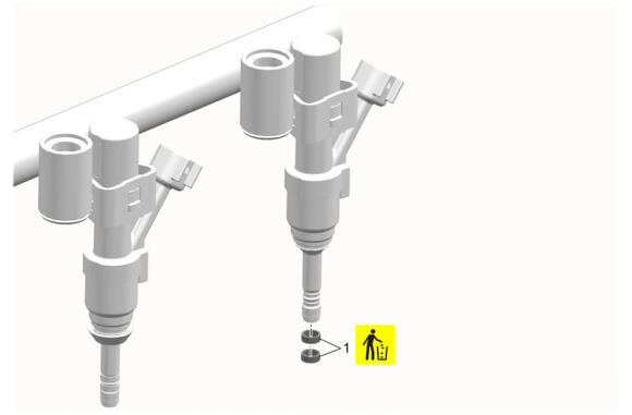
- Fuel Injector Nozzle Housing Seal (1) - Remove and DISCARD [8x]
 Courtesy of GENERAL MOTORS COMPANY Courtesy of GENERAL MOTORS COMPANY
|
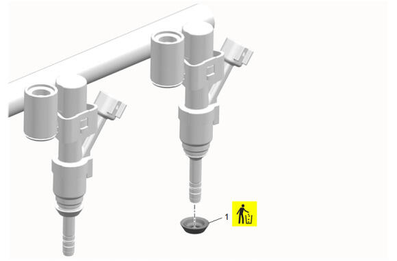
- Fuel Injector Seal (1) - Remove and DISCARD [4x]
- Clean the cylinder head around the fuel injectors on bank 2 of any dirt or buildup.
 Courtesy of GENERAL MOTORS COMPANY Courtesy of GENERAL MOTORS COMPANY
|
NOTE:
The bank 2 fuel injection fuel rail bolts are retained in the bank 2 fuel injection fuel rail and may be difficult to remove.
- Remove the 4 bank 2 fuel injection fuel rail bolts (1).
Courtesy of GENERAL MOTORS COMPANY
|
NOTE:
- In some cases, the fuel injectors may be difficult to remove because of heavy carbon build-up or other factors. If the fuel injectors are difficult to remove, apply solvent to the base of the fuel injector bores, and allow adequate soaking time, to loosen the fuel injectors.
- The bank 2 fuel injection fuel rail and fuel injectors are removed as an assembly.
- To prevent material from entering the combustions chambers make sure the area around each fuel injector is clean and free of debris before the fuel injectors are removed from the fuel injector bores.
- Install 2 sets of EN-49248 Injector Rail Assembly Remover (1) on bank 2.
- Install one EN-49248 Injector Rail Assembly Remover (1) in each of the 4 bank 2 fuel injection fuel rail bolt bores.
- Turn each EN-49248 Injector Rail Assembly Remover (1) an even amount to pull the fuel injection fuel rail bank 2 (2) and fuel injectors out evenly.
CAUTION:
- Remove the fuel rail assembly carefully in order to prevent damage to the injector electrical connector terminals and the injector spray tips. Support the fuel rail after the fuel rail is removed in order to avoid damaging the fuel rail components.
- Cap the fittings and plug the holes when servicing the fuel system in order to prevent dirt and other contaminants from entering open pipes and passages.
- Simultaneously lift both ends of the bank 2 fuel injection fuel rail (2) and remove from the right side cylinder head.
Courtesy of GENERAL MOTORS COMPANY
|
- Fuel Injector Nozzle Housing Seal (1) - Remove and DISCARD [8x]
Courtesy of GENERAL MOTORS COMPANY
|
- Fuel Injector Seal (1) - Remove and DISCARD [4x]
 Courtesy of GENERAL MOTORS COMPANY Courtesy of GENERAL MOTORS COMPANY
|
- Engine Wiring Harness Bolt (1) - Remove [2x]
 Courtesy of GENERAL MOTORS COMPANY Courtesy of GENERAL MOTORS COMPANY
|
- Valve Rocker Arm Oil Control Valve Extension Harness (1) @ Valve Rocker Arm Oil Control Valve Harness - Disconnect
 Courtesy of GENERAL MOTORS COMPANY Courtesy of GENERAL MOTORS COMPANY
|
- Knock Sensor Shield Bolt (1) - Remove
- Knock Sensor Shield (2) - Remove
 Courtesy of GENERAL MOTORS COMPANY Courtesy of GENERAL MOTORS COMPANY
|
- Knock Sensor Bolt (1) - Remove
- Knock Sensor - Left Side (2) - Remove
 Courtesy of GENERAL MOTORS COMPANY Courtesy of GENERAL MOTORS COMPANY
|
- {If equipped} Engine Coolant Heater (1) - Remove
 Courtesy of GENERAL MOTORS COMPANY Courtesy of GENERAL MOTORS COMPANY
|
- Knock Sensor Bolt (1) - Remove
- Knock Sensor - Right Side (2) - Remove