- Knock Sensor - Right Side (2) - Install
- Knock Sensor Bolt (1) - Install and tighten - Fastener Specifications
 Courtesy of GENERAL MOTORS COMPANY Courtesy of GENERAL MOTORS COMPANY
|
NOTE:
Ensure proper use of room temperature vulcanizing (RTV) sealant.
- Apply sealant to the engine coolant heater (1) if equipped. Adhesives, Fluids, Lubricants, and Sealers
- {If equipped} Engine Coolant Heater (1) - Install and tighten - FASTENER SPECIFICATIONS
 Courtesy of GENERAL MOTORS COMPANY Courtesy of GENERAL MOTORS COMPANY
|
- Knock Sensor - Left Side (2) - Install
- Knock Sensor Bolt (1) - Install and tighten - Fastener Specifications
 Courtesy of GENERAL MOTORS COMPANY Courtesy of GENERAL MOTORS COMPANY
|
- Knock Sensor Shield (2) - Install
- Knock Sensor Shield Bolt (1) - Install and tighten - Fastener Specifications
 Courtesy of GENERAL MOTORS COMPANY Courtesy of GENERAL MOTORS COMPANY
|
- Valve Rocker Arm Oil Control Valve Extension Harness (1) @ Valve Rocker Arm Oil Control Valve Harness - Connect
 Courtesy of GENERAL MOTORS COMPANY Courtesy of GENERAL MOTORS COMPANY
|
- Engine Wiring Harness Bolt (1) - Install and tighten [2x] - Fastener Specifications
 Courtesy of GENERAL MOTORS COMPANY Courtesy of GENERAL MOTORS COMPANY
|
NOTE:
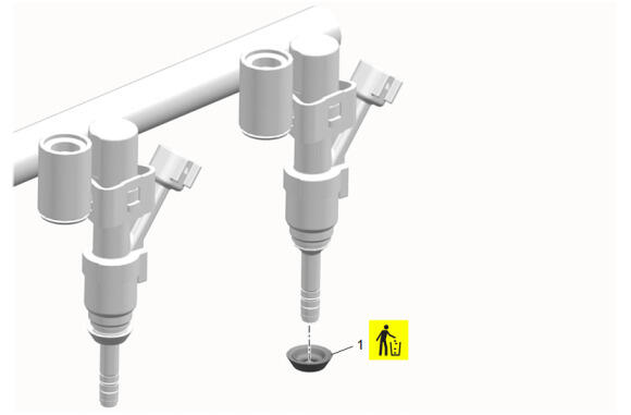
The 4 bank 2 fuel injector seals (1) should be clean and free of debris prior to installation.
NOTE:
Note: Do NOT use any type of lubricant when installing the NEW 4 bank 2 fuel injector seals (1) on the fuel injector.
- Fuel Injector Seal (1) - Install NEW [4x]
 Courtesy of GENERAL MOTORS COMPANY Courtesy of GENERAL MOTORS COMPANY
|
NOTE:
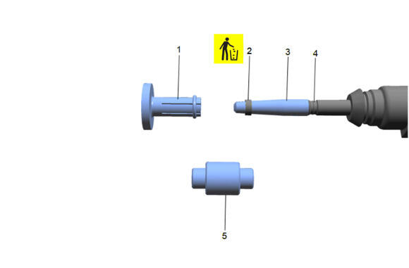
Do NOT use any type of lubricant when installing NEW seals (2) on the injector.
- Install EN-51955-1 Long Protector (3) onto the fuel injector tip. Place a NEW seal (2) on EN-51955-1 Long Protector.
- Using EN-51955-4 Pusher (1), install the seal onto the first recessed area (4) of the fuel injector and remove EN-51955-4 Pusher.
NOTE:
The EN-51955-5 Sizer is two sided, and either direction will size the seal correctly.
- Compress the seal with your fingers, then resize the seal using the EN-51955-5 Sizer (5).
 Courtesy of GENERAL MOTORS COMPANY Courtesy of GENERAL MOTORS COMPANY
|
NOTE:
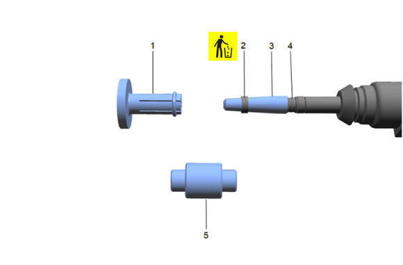
Do NOT use any type of lubricant when installing NEW seals (2) on the injector.
- Install EN-51955-2 Short Protector (3) onto the fuel injector tip. Place a NEW seal (2) on EN-51955-2 Short Protector.
- Using EN-51955-4 Pusher (1), install the seal onto the second recessed area (4) of the fuel injector.
NOTE:
The EN-51955-5 Sizer is two sided, and either direction will size the seal correctly.
- Compress the seal with your fingers, then resize the seal using the EN-51955-5 Sizer (5).
- Inspect the NEW fuel injector nozzle housing seals on ALL injectors, ensuring the seals are seated correctly. All seals must be fixed tight, and accurately to the fuel injector nozzle, with no overlap, buckling, or corrugation present. Replace any seal that is incorrectly seated on the fuel injector nozzle with a NEW seal.
 Courtesy of GENERAL MOTORS COMPANY Courtesy of GENERAL MOTORS COMPANY
|
NOTE:
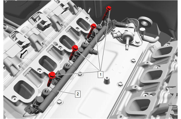
The 4 bank 2 fuel injection fuel rail bolts (1) are retained into the fuel injection fuel rail (2). Care should be taken to ensure that the threadlocker is installed after the 4 bank 2 fuel injection fuel rail bolts (1) are installed to the bank 2 fuel injection fuel rail (2)
- Install the 4 fuel injection fuel rail bolts (1) to the bank 2 fuel injection fuel rail (2).
- Prepare the 4 bank 2 fuel injection fuel rail bolts (1) for installation as follows:
- Remove any loose cured adhesive from the external threads of the components using a lint free cloth.
- Thread the cleaned components into the internal mating threads and remove to loosen trapped cured adhesive.
- Apply thread locking adhesive to the external threads of the components. Adhesives, Fluids, Lubricants, and Sealers
- Ensure there are no gaps in the thread locking adhesive once applied to the component.
- Install the bank 2 fuel injection fuel rail (2) to the right cylinder head.
- Fuel Injection Fuel Rail Bolt (1) - Hand tighten [4x]
- Fuel Injection Fuel Rail Bolt (1) - Tighten [4x] - Fastener Specifications
- Connect the electrical wiring harness connectors to the bank 2 fuel injection fuel rail.
Courtesy of GENERAL MOTORS COMPANY
|
NOTE:
The 4 bank 1 fuel injector seals (1) should be clean and free of debris prior to installation.
NOTE:
Do NOT use any type of lubricant when installing the NEW 4 bank 1 fuel injector seals (1) on the fuel injector.
- Fuel Injector Seal (1) - Install NEW [4x]
Courtesy of GENERAL MOTORS COMPANY
|
NOTE:
Do NOT use any type of lubricant when installing NEW seals (2) on the injector.
- Install EN-51955-1 Long Protector (3) onto the fuel injector tip. Place a NEW seal (2) on EN-51955-1 Long Protector.
- Using EN-51955-4 Pusher (1), install the seal onto the first recessed area (4) of the fuel injector and remove EN-51955-4 Pusher.
NOTE:
The EN-51955-5 Sizer is two sided, and either direction will size the seal correctly
- .Compress the seal with your fingers, then resize the seal using the EN-51955-5 Sizer (5).
Courtesy of GENERAL MOTORS COMPANY
|
NOTE:
Do NOT use any type of lubricant when installing NEW seals (2) on the injector.
- Install EN-51955-2 Short Protector (3) onto the fuel injector tip. Place a NEW seal (2) on EN-51955-2 Short Protector.
- Using EN-51955-4 Pusher (1), install the seal onto the second recessed area (4) of the fuel injector.
NOTE:
The EN-51955-5 Sizer is two sided, and either direction will size the seal correctly.
- Compress the seal with your fingers, then resize the seal using the EN-51955-5 Sizer (5).
- Inspect the NEW fuel injector nozzle housing seals on ALL injectors, ensuring the seals are seated correctly. All seals must be fixed tight, and accurately to the fuel injector nozzle, with no overlap, buckling, or corrugation present. Replace any seal that is incorrectly seated on the fuel injector nozzle with a NEW seal.
 Courtesy of GENERAL MOTORS COMPANY Courtesy of GENERAL MOTORS COMPANY
|
NOTE:
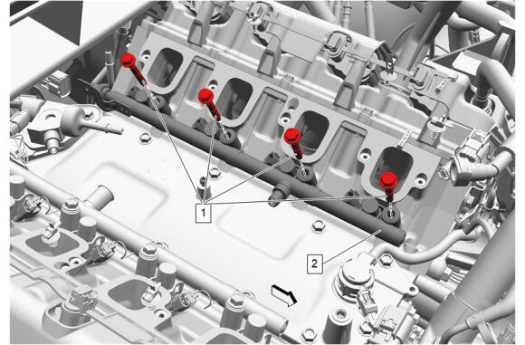
The 4 bank 1 fuel injection fuel rail bolts (1) are retained into the fuel injection fuel rail (2). Care should be taken to ensure that the threadlocker is installed after the 4 bank 1 fuel injection fuel rail bolts (1) are installed to the bank 1 fuel injection fuel rail (2).
- Install the 4 fuel injection fuel rail bolts (1) to the bank 1 fuel injection fuel rail (2).
- Prepare the 4 bank 1 fuel injection fuel rail bolts (1) for installation as follows:
- Remove any loose cured adhesive from the external threads of the components using a lint free cloth.
- Thread the cleaned components into the internal mating threads and remove to loosen trapped cured adhesive.
- Apply thread locking adhesive to the external threads of the components. Adhesives, Fluids, Lubricants, and Sealers
- Ensure there are no gaps in the thread locking adhesive once applied to the component.
- Install the bank 1 fuel injection fuel rail (2) to the left cylinder head.
- Fuel Injection Fuel Rail Bolt (1) - Hand tighten [4x]
- Fuel Injection Fuel Rail Bolt (1) - Tighten [4x] - Fastener Specifications
- Connect the electrical wiring harness connectors to the bank 1 fuel injection fuel rail.
 Courtesy of GENERAL MOTORS COMPANY Courtesy of GENERAL MOTORS COMPANY
|
NOTE:
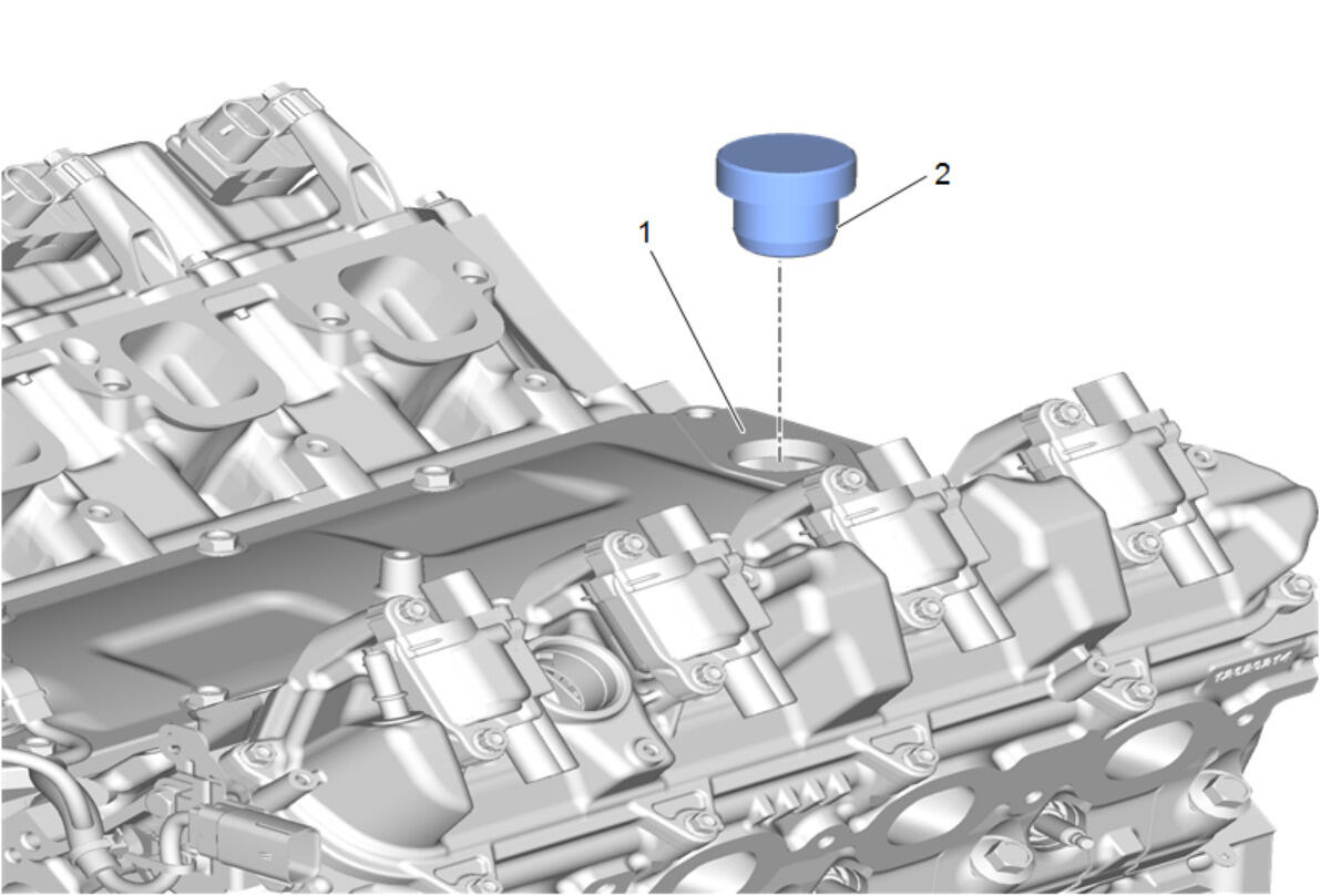
Note: The camshaft must be in the base circle position before the fuel pump is installed.
- Using EN-51092 Fuel Pump Installation Gauge (2) ensure that the camshaft lobe is in the base circle position. At base circle position, the EN-51092 Fuel Pump Installation Gauge (2) will be flush with the top surface of the lifter oil manifold assembly (1).
 Courtesy of GENERAL MOTORS COMPANY Courtesy of GENERAL MOTORS COMPANY
|
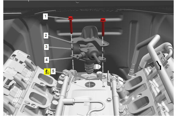
- Ensure the 2 plastic fastener retainers (3) are installed in the fuel pump mounting holes before installing the fuel pump.
- Fuel Pump Bracket Gasket (5) - Install NEW
NOTE:
Ensure that the fuel pump roller lifter is oriented properly, the camshaft is at base circle and the number 1 piston is at top dead center (TDC) on the exhaust stroke.
- Fuel Pump (4) - Install
- Fuel Pump Cover (2) - Install
CAUTION:
Alternately hand-tighten the fuel pump bolts one turn at a time until the pump is fully seated. Trying to draw down the pump without even side-to-side tightening may result in pump plunger damage.
- Fuel Pump Bolt (1) - Install and hand tighten [2x]
- Fuel Pump Bolt (1) - Tighten [2x] - Fastener Specifications
- Reposition the fuel pump and fuel injector wiring harness and connect as necessary.
 Courtesy of GENERAL MOTORS COMPANY Courtesy of GENERAL MOTORS COMPANY
|
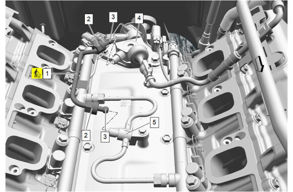
NOTE:
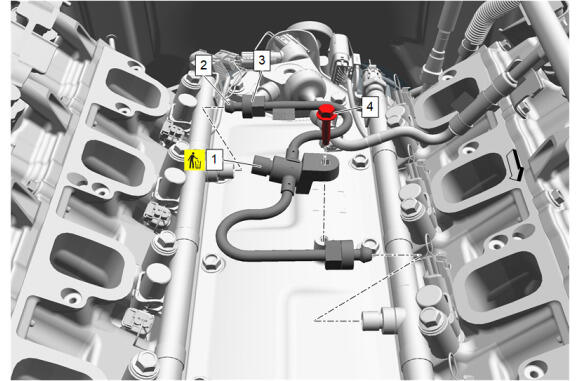
Do NOT reuse the fuel feed intermediate pipe (1). If the 2 fuel feed intermediate pipe nuts (3) are loosened or the fuel feed intermediate pipes are removed, the fuel feed intermediate pipes MUST be replaced.
- Fuel Feed Intermediate Pipe (1) - Install NEW
- Slide the 2 fuel feed intermediate pipe nuts (3) back along fuel feed intermediate pipe (1) to reveal the 2 formed ends (2) of the fuel feed intermediate pipe (1).
- Carefully install the 2 formed ends (2) of the fuel feed intermediate pipe (1) into the sockets of the left and right fuel injection fuel rail. Take care not to hit the 2 formed ends (2) of the fuel feed intermediate pipe (1) on the threaded sockets on the fuel injection fuel rails.
- Hold the fuel feed intermediate pipe (1) firmly in place and hand tighten the 2 fuel feed intermediate pipe nuts (3).
- Fuel Feed Pipe Bolt (4) - Tighten - Fastener Specifications
- Fuel Feed Intermediate Pipe Nut (3) - Tighten [2x] - Fastener Specifications
 Courtesy of GENERAL MOTORS COMPANY Courtesy of GENERAL MOTORS COMPANY
|
NOTE:
Do NOT reuse the fuel feed intermediate pipe (1). If the 2 fuel feed intermediate pipe nuts (2) are loosened or the fuel feed intermediate pipes are removed, the fuel feed intermediate pipes MUST be replaced.
- Fuel Feed Intermediate Pipe (1) - Install NEW
- Slide the 2 fuel feed intermediate pipe nuts (2) back along fuel feed intermediate pipe (1) to reveal the 2 formed ends (3) of the fuel feed intermediate pipe (1).
- Carefully install the 2 formed ends (3) of the fuel feed intermediate pipe (1) into the sockets of the fuel pump (4) and the fuel feed intermediate pipe (5). Take care not to hit the 2 formed ends (3) of the fuel feed intermediate pipe (1) on the threaded sockets of the fuel pump (4) and fuel feed intermediate pipe (5).
- Hold the fuel feed intermediate pipe (1) firmly in place and hand tighten the 2 fuel feed intermediate pipe nuts (2).
- Fuel Feed Intermediate Pipe Nut (2) - Tighten [2x] - Fastener Specifications
 Courtesy of GENERAL MOTORS COMPANY Courtesy of GENERAL MOTORS COMPANY
|
- Exhaust Manifold Gasket (1) - Install NEW
- Exhaust Manifold - Right Side (3) - Install
- Exhaust Manifold Bolt (2) - Install NEW and hand tighten [5x]
- Exhaust Manifold Bolt (2) - Tighten [5x] - Fastener Specifications
 Courtesy of GENERAL MOTORS COMPANY Courtesy of GENERAL MOTORS COMPANY
|
- Exhaust Manifold Heat Shield - Right Side (2) - Install
- Exhaust Manifold Heat Shield Bolt (1) - Install and tighten [3x] - Fastener Specifications
 Courtesy of GENERAL MOTORS COMPANY Courtesy of GENERAL MOTORS COMPANY
|
- Oil Level Indicator Seal (2) - Install NEW
- Install the oil level indicator, oil level indicator tube and oil level indicator seal as an assembly (1)
 Courtesy of GENERAL MOTORS COMPANY Courtesy of GENERAL MOTORS COMPANY
|
- Oil Level Indicator Tube Bolt (1) - Install and tighten - Fastener Specifications
 Courtesy of GENERAL MOTORS COMPANY Courtesy of GENERAL MOTORS COMPANY
|
- Exhaust Manifold Gasket (1) - Install NEW
- Exhaust Manifold - Left Side (3) - Install
- Exhaust Manifold Bolt (2) - Install NEW and hand tighten [5x]
- Exhaust Manifold Bolt (2) - Tighten [5x] - Fastener Specifications
 Courtesy of GENERAL MOTORS COMPANY Courtesy of GENERAL MOTORS COMPANY
|
- Exhaust Manifold Heat Shield - Left Side (2) - Install
- Exhaust Manifold Heat Shield Bolt (1) - Install and tighten [3x] - Fastener Specifications
 Courtesy of GENERAL MOTORS COMPANY Courtesy of GENERAL MOTORS COMPANY
|
- Ignition Coil (2) - Install [4x]
- Ignition Coil Bolt (1) - Install and tighten [8x] - Fastener Specifications
- Connect the ignition coil electrical connectors.
 Courtesy of GENERAL MOTORS COMPANY Courtesy of GENERAL MOTORS COMPANY
|
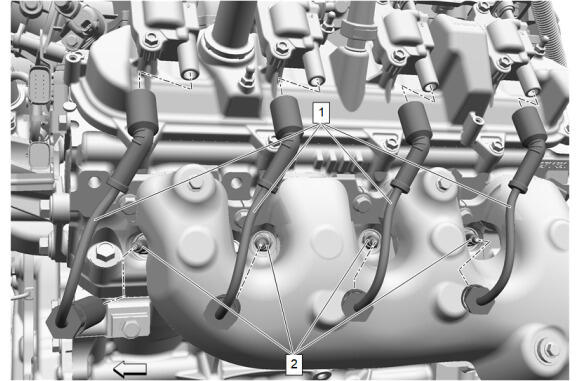
- Inspect the inside of the spark plug rubber boots for a thin, even coat of grease. If there is no grease present or additional grease is necessary, apply a thin coating of dielectric grease evenly to the inside of the spark plug rubber boots up to a depth of 15 mm from the end of the boots. Adhesives, Fluids, Lubricants, and Sealers
- Push the 4 boots of the spark plug wires (1) onto the 4 ignition coils (2) until 2 audible clicks are heard.
 Courtesy of GENERAL MOTORS COMPANY Courtesy of GENERAL MOTORS COMPANY
|
- Push the 4 boot of the spark plug wires (1) onto the 4 gas engine ignition spark plugs (2) until 2 audible clicks are heard.
 Courtesy of GENERAL MOTORS COMPANY Courtesy of GENERAL MOTORS COMPANY
|
- Ignition Coil (2) - Install [4x]
- Ignition Coil Bolt (1) - Install and tighten [8x] - Fastener Specifications
- Connect the ignition coil electrical connectors.
Courtesy of GENERAL MOTORS COMPANY
|
- Inspect the inside of the spark plug rubber boots for a thin, even coat of grease. If there is no grease present or additional grease is necessary, apply a thin coating of dielectric grease evenly to the inside of the spark plug rubber boots up to a depth of 15 mm from the end of the boots. Adhesives, Fluids, Lubricants, and Sealers
- Push the 4 boots of the spark plug wires (1) onto the 4 ignition coils (2) until 2 audible clicks are heard.
Courtesy of GENERAL MOTORS COMPANY
|
- Push the boot of the 4 spark plug wires (1) onto the 4 gas engine ignition spark plugs (2) until 2 audible clicks are heard.
 Courtesy of GENERAL MOTORS COMPANY Courtesy of GENERAL MOTORS COMPANY
|
- Valve Rocker Arm Cover Insulator (3) - Install
- Install the 3 upper intake manifold sight shield grommets (1) to the 3 valve rocker arm cover insulator retainers (2).
 Courtesy of GENERAL MOTORS COMPANY Courtesy of GENERAL MOTORS COMPANY
|
- Valve Rocker Arm Cover Insulator (3) - Install
- Install the 3 upper intake manifold sight shield grommets (2) to the 3 valve rocker arm cover insulator retainers (1).
 Courtesy of GENERAL MOTORS COMPANY Courtesy of GENERAL MOTORS COMPANY
|
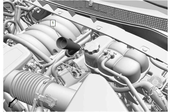
- Lubricate the oil filler tube seal (2) with clean engine oil. **Adhesives, Fluids, Lubricants, and Sealers
 Courtesy of GENERAL MOTORS COMPANY Courtesy of GENERAL MOTORS COMPANY
|
- Install the oil filler tube (1) to the valve rocker arm cover and rotate clockwise to install.
 Courtesy of GENERAL MOTORS COMPANY Courtesy of GENERAL MOTORS COMPANY
|
- Install the belt idler pulley and belt idler pulley bracket (2) as an assembly.
- Belt Idler Pulley Bracket Bolt (1) - Install and tighten [3x] - Fastener Specifications
 Courtesy of GENERAL MOTORS COMPANY Courtesy of GENERAL MOTORS COMPANY
|
- Engine Mount - Left Side (2) - Install
- Prepare the 4 engine mount engine side bolts for installation as follows:
- Remove any loose cured adhesive from the external threads of the components using a lint free cloth.
- Thread the cleaned components into the internal mating threads and remove to loosen trapped cured adhesive.
- Apply thread locking adhesive to the external threads of the components. Adhesives, Fluids, Lubricants, and Sealers
- Ensure there are no gaps in the thread locking adhesive once applied to the component.
- Engine Mount Engine Side Bolt - Left Side (1) - Install and hand tighten [4x]
- Engine Mount Engine Side Bolt - Left Side (1) - Tighten [4x] - Fastener Specifications
 Courtesy of GENERAL MOTORS COMPANY Courtesy of GENERAL MOTORS COMPANY
|
- Engine Mount - Right Side (2) - Install
- Prepare the 4 engine mount engine side bolts (1) for installation as follows:
- Remove any loose cured adhesive from the external threads of the components using a lint free cloth.
- Thread the cleaned components into the internal mating threads and remove to loosen trapped cured adhesive.
- Apply thread locking adhesive to the external threads of the components. Adhesives, Fluids, Lubricants, and Sealers
- Ensure there are no gaps in the thread locking adhesive once applied to the component.
- Engine Mount Engine Side Bolt - Right Side (1) - Install and hand tighten [4x]
- Engine Mount Engine Side Bolt - Right Side (1) - Tighten [4x] - Fastener Specifications
 Courtesy of GENERAL MOTORS COMPANY Courtesy of GENERAL MOTORS COMPANY
|
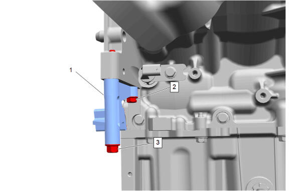
- EN-42386-A Flywheel Holding Tool (1) - Install
- Install 1 M10-1.5 x 120 mm (3) bolt and 1 M10-1.5 x 45 mm bolt (2).
- Tighten the 2 bolts (2, 3) to 50 N.m (37 lb ft).
 Courtesy of GENERAL MOTORS COMPANY Courtesy of GENERAL MOTORS COMPANY
|
NOTE:
The automatic transmission flex plate does not use a locating pin for alignment and will not initially seat against the crankshaft flange, but will be pulled onto the crankshaft by the automatic transmission flex plate bolts. This procedure requires a 3 stage tightening process.
- Automatic Transmission Flex Plate (1) - Install
 Courtesy of GENERAL MOTORS COMPANY Courtesy of GENERAL MOTORS COMPANY
|
- Due to the unknown shelf life of the adhesive patch, prepare the 8 NEW automatic transmission flex plate bolts (1) as follows:
- Remove any loose cured adhesive from the external threads of the components using a lint free cloth.
- Thread the cleaned components into the internal mating threads and remove to loosen trapped cured adhesive.
- Apply thread locking adhesive to the external threads of the components. Adhesives, Fluids, Lubricants, and Sealers
- Ensure there are no gaps in the thread locking adhesive once applied to the component.
CAUTION:
This vehicle is equipped with torque-to-yield or single use fasteners. Install a NEW torque-to-yield or single use fastener when installing this component. Failure to replace the torque-to-yield or single use fastener could cause damage to the vehicle or component
- Automatic Transmission Flex Plate Bolt (1) - Install NEW and hand tighten [8x]
- Automatic Transmission Flex Plate Bolt (1) - Tighten in sequence [8x] - Fastener Specifications
 Courtesy of GENERAL MOTORS COMPANY Courtesy of GENERAL MOTORS COMPANY
|
- Remove the M10-1.5 x 120 mm bolt (3) and the M10-1.5 x 45 mm bolt (2).
- EN-42386-A Flywheel Holding Tool (1) - Remove
 Courtesy of GENERAL MOTORS COMPANY Courtesy of GENERAL MOTORS COMPANY
|
- Install EN-36857 Engine Lift Bracket (1) using EN-52059 Engine Support Fixture Adapter Bolt - M10 (2) to the cylinder head as shown.
 Courtesy of GENERAL MOTORS COMPANY Courtesy of GENERAL MOTORS COMPANY
|
- Install EN-36857 Engine Lift Bracket (1) using EN-52059 Engine Support Fixture Adapter Bolt - M10 (2) to the cylinder head as shown.
- Install a suitable chain to the two engine lift brackets to support the engine.
 Courtesy of GENERAL MOTORS COMPANY Courtesy of GENERAL MOTORS COMPANY
|
- Using a suitable engine lifting device, remove the engine (1) from the engine stand (2). See Engine Removal and Installation (1 Of 3) ENGINE REMOVAL AND INSTALLATION (2 OF 3)
, or ENGINE REMOVAL AND INSTALLATION (3 OF 3)