Installation Procedure
- Position the generator and starter cable to the vehicle.
- Raise the vehicle.
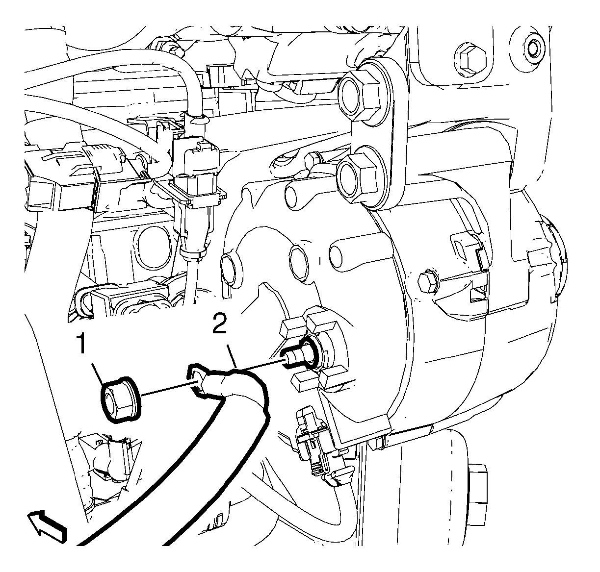
- Install the generator positive cable (2) to the generator.
 Courtesy of GENERAL MOTORS COMPANY
- Install the positive cable nut (1) and tighten to 13 N.m (115 lb in).
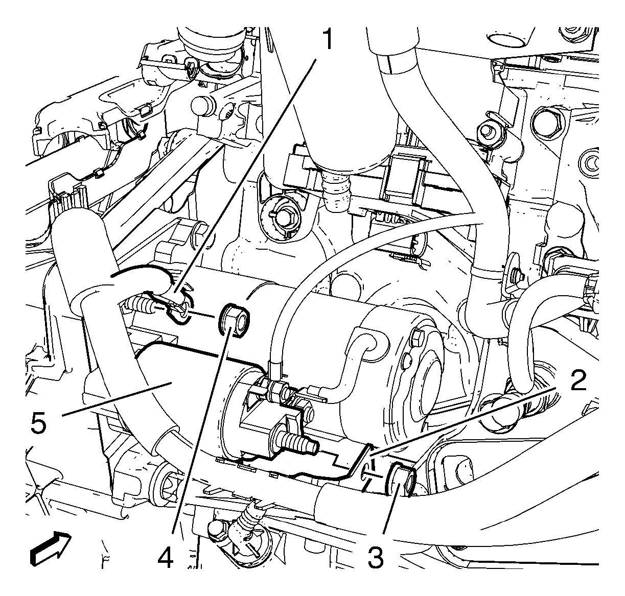
- Install the starter ground cable (1) to the starter (5).
 Courtesy of GENERAL MOTORS COMPANY
- Install the starter ground cable nut (4) and tighten to 17 N.m (13 lb ft)
- Install the starter positive cable (2) and tighten the starter positive cable nut (3) to 13 N.m (115 lb in).
- If equipped, install the engine shield. Refer to Engine Shield Replacement
.
- Lower the vehicle.
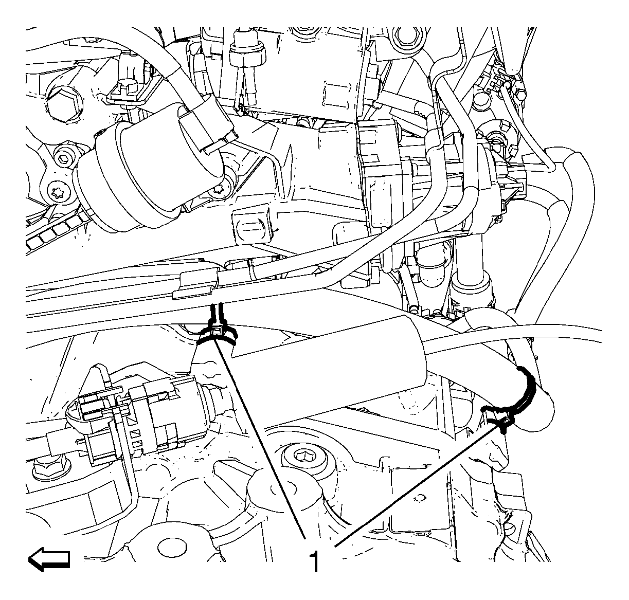
- Clip in the 2 generator and starter cable retainers (1) to the transmission.
 Courtesy of GENERAL MOTORS COMPANY
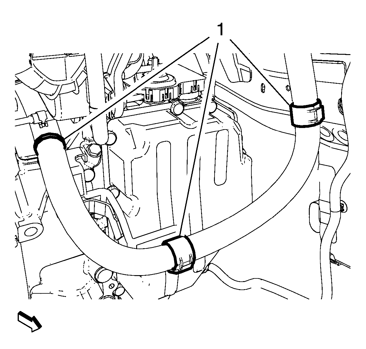
- Clip in the 3 generator and starter cable retainers (1) to the body and to the transmission.
 Courtesy of GENERAL MOTORS COMPANY
- Install the battery ground cable (2).
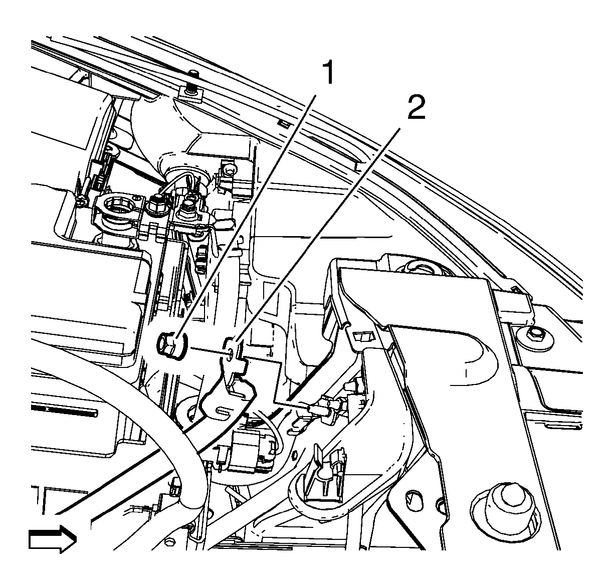 Courtesy of GENERAL MOTORS COMPANY
- Install the battery ground cable nut (1) and tighten to 9 N.m (80 lb in).
- Install the battery positive cable (3) to the battery.
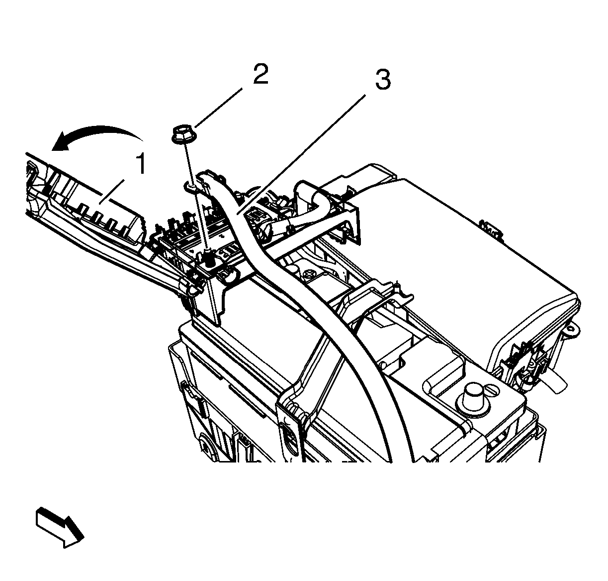 Courtesy of GENERAL MOTORS COMPANY
- Install the battery positive cable nut (2) and tighten to 12 N.m (106 lb in).
- Close the battery fuse box cover (1) and lock the retaining tabs (2, 3)
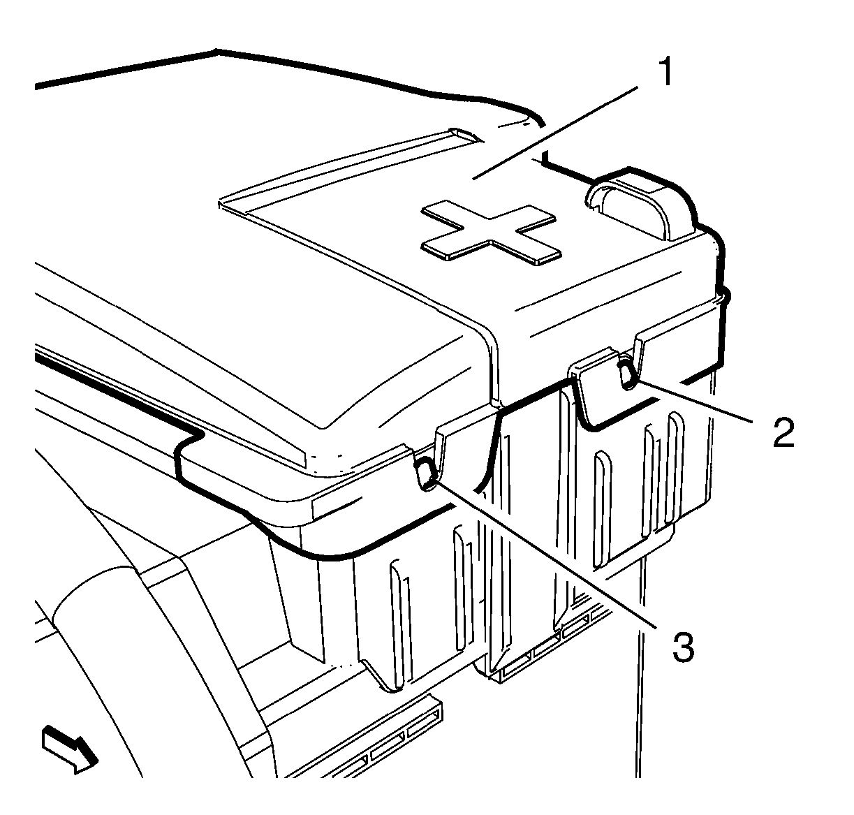 Courtesy of GENERAL MOTORS COMPANY
- Install the engine control module. Refer to Engine Control Module Replacement
.
- Connect the battery negative cable. Refer to Battery Negative Cable Disconnection and Connection .