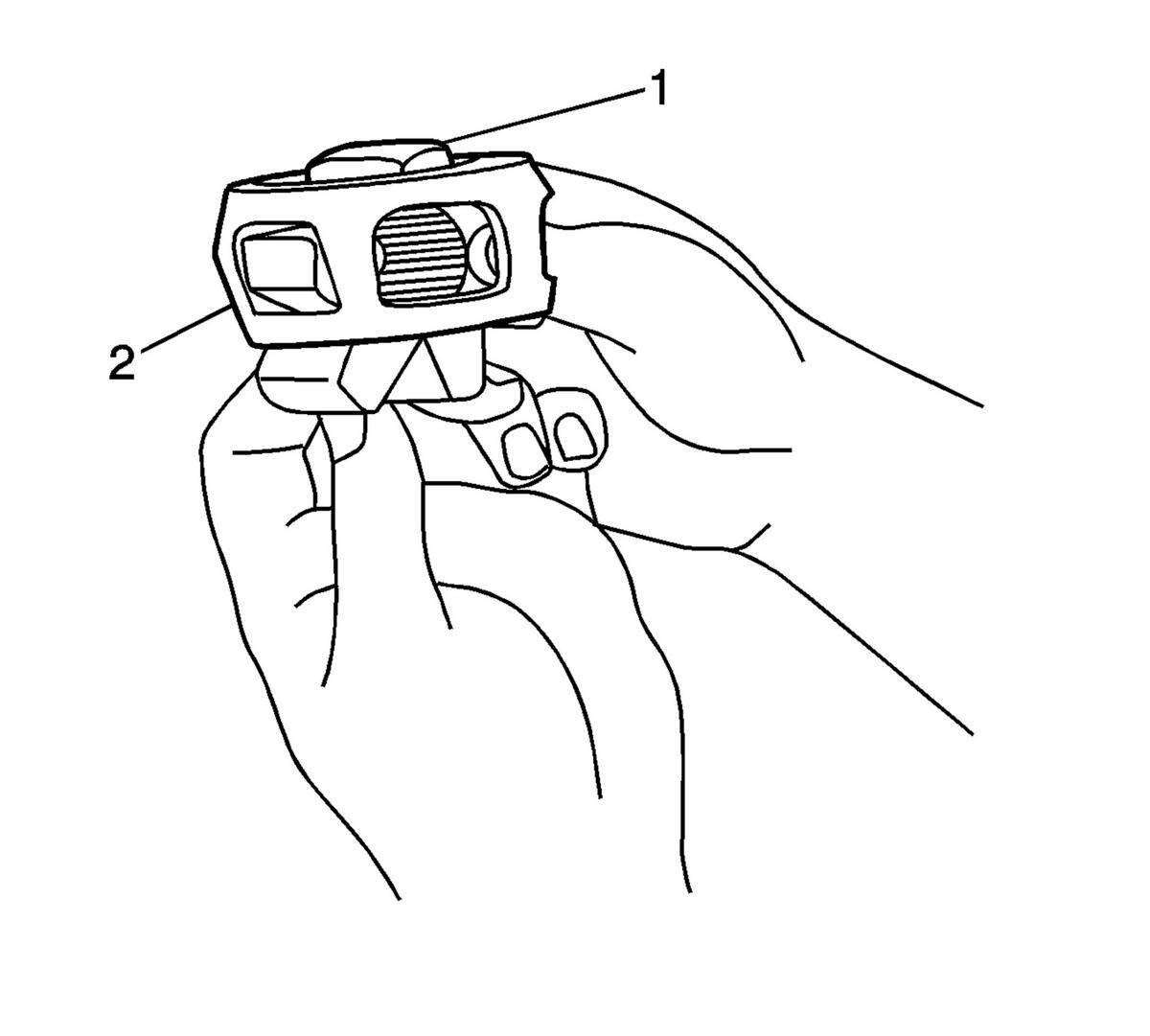
- Position the cage (2) so that the larger radius corners of the cage windows are up.
 Courtesy of GENERAL MOTORS COMPANY
- Position the inner race (1) 90 degrees to the centerline of the cage (2).
- Insert the inner race (1) through the bottom of the cage (2).
- Align the lands of the inner race (1) with the windows of the cage (2).
- Move the inner race (1) land into the cage window (2).
- Rotate the inner race (1) down and remove it from the cage (2).
- Rotate the inner race (1) within the cage (2) so that the grooved surface of the inner race (1) is facing up.
- Align the inner race (1) ball bearing tracks with the cage (2) windows.
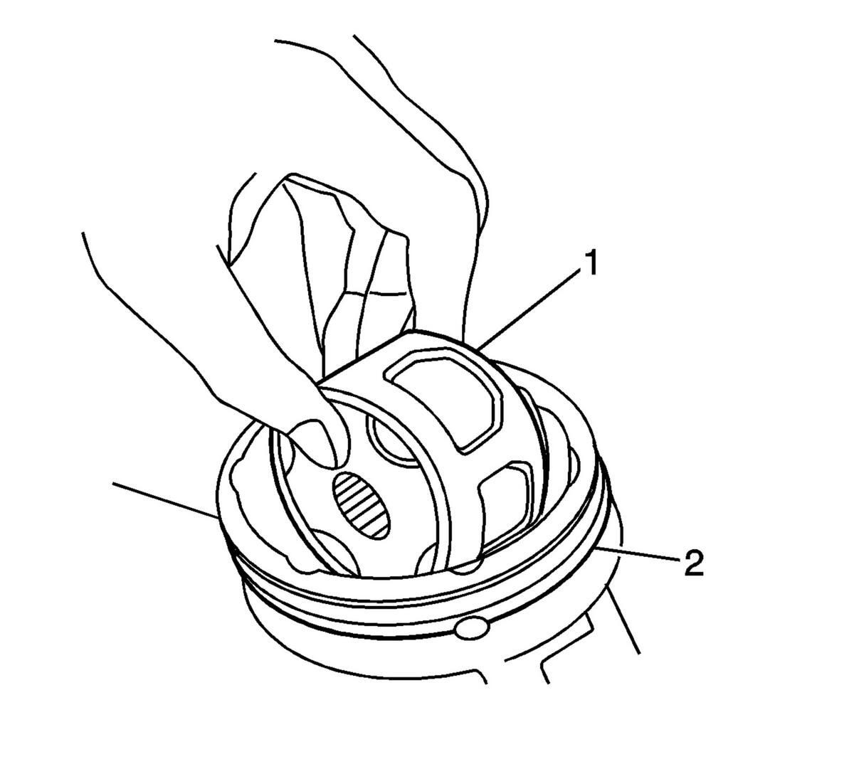
- Wrap a clean shop towel around the CV joint outer race splined shaft.
 Courtesy of GENERAL MOTORS COMPANY
- Place the outer race (2) vertically in a bench vise.
- Position the cage (1) and the inner race at a 90 degrees to the centerline of the outer race (2).
- With the inner race and the cage (1) assembly in a vertical position, insert the cage and the inner race into the outer race (2).
- Position the cage (2) and the inner race so that they are level in the vise.
 Courtesy of GENERAL MOTORS COMPANY
NOTE:
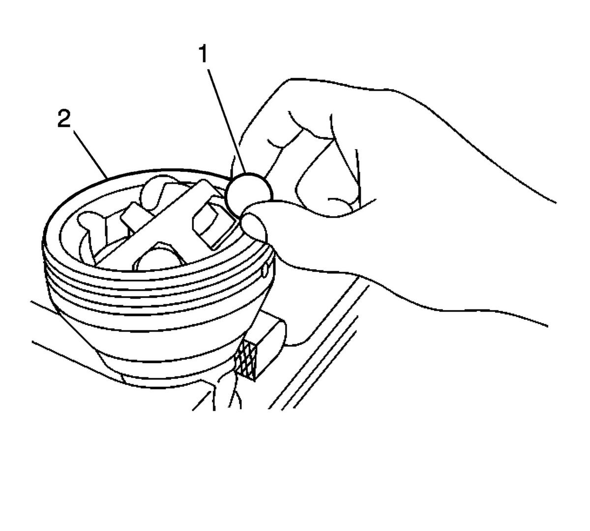
The larger radius corners of the cage windows should be positioned up and the grooved surface of the inner race should be visible.
- Rotate the appropriate component(s) and align the cage windows and the inner race ball bearing (1) tracks with the outer race ball bearing tracks.
- Position a cage window and the inner race ball bearing track for the ball bearing installation.
- Press down on the cage following one of the outer race ball bearing (1) tracks.
NOTE:
When performing the following procedure, the opposing cage (2) window and the inner ball bearing (1) track will be accessible for the ball bearing installation.
- Install the ball bearing through the cage window onto the inner race ball bearing (1) track.
- After the first ball bearing (1) has been installed, use a brass drift and a hammer and gently tap the cage in order to drive the cage and the inner race down completely in the outer race.
NOTE:
The following service procedure will have to be performed after each ball bearing (1) has been installed.
- Position the cage and the inner race so that they are level.
NOTE:
After the ball bearing (1) has been installed, there should be NO GAP between the ball bearing and the inner race.
- Using a plastic hammer, lightly tap the ball bearing (1) into place.
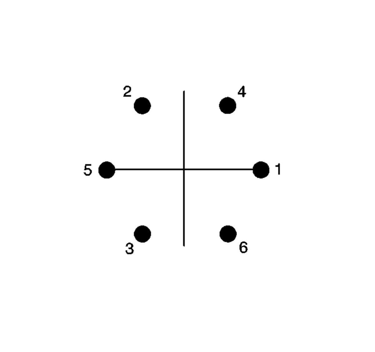
- Install the ball bearings in sequence.
 Courtesy of GENERAL MOTORS COMPANY
- Repeat steps 18 thru 20 until all the ball bearings are installed.
- Install the outer CV joint and boot on the wheel drive shaft. Refer to Front Wheel Drive Shaft Outer Joint and Boot Replacement .