Installation Procedure
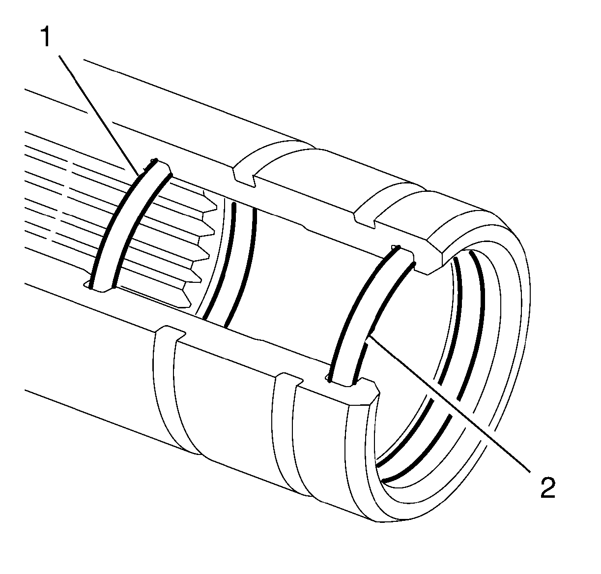
- Install a NEW inner orange sealing ring (1) to the rear notch in the front wheel drive intermediate shaft.
 Courtesy of GENERAL MOTORS COMPANY
- Install a NEW outer black sealing ring (2) to the front notch in the front wheel drive intermediate shaft.
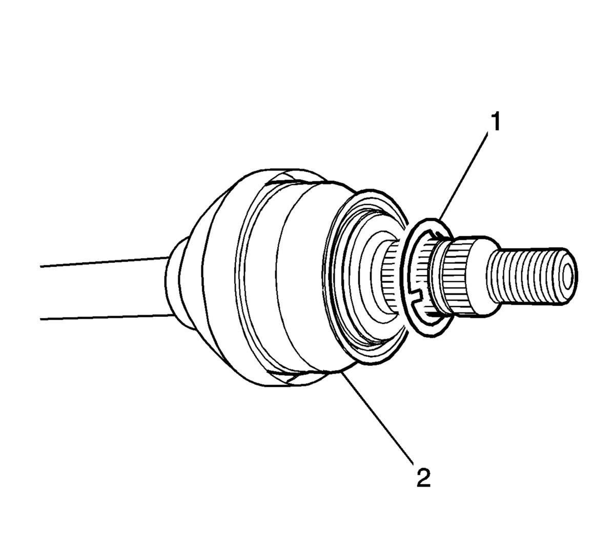
- Install a NEW washer (1) to the wheel drive shaft (2).
 Courtesy of GENERAL MOTORS COMPANY
- Grease the intermediate shaft splines. Refer to Adhesives, Fluids, Lubricants and Sealers .
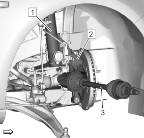
- Install the wheel drive shaft (3) to the vehicle.
 Courtesy of GENERAL MOTORS COMPANY
- Confirm that the front wheel drive shaft retaining ring is properly seated by holding the inner housing and pull the inner housing outward.
- Install the front wheel drive shaft into the front wheel bearing/hub.
- Install the ball joint to the steering knuckle. Refer to Lower Control Arm Replacement
.
- Install the outer tie rod assembly at the steering knuckle. Refer to Steering Linkage Outer Tie Rod Replacement
.
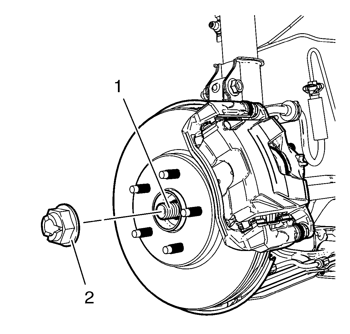
- Install the wheel drive shaft nut (2) to the wheel drive shaft (1) tighten in 3 passes.
 Courtesy of GENERAL MOTORS COMPANY
- Insert a drift or punch in the cooling fins of the brake rotor.
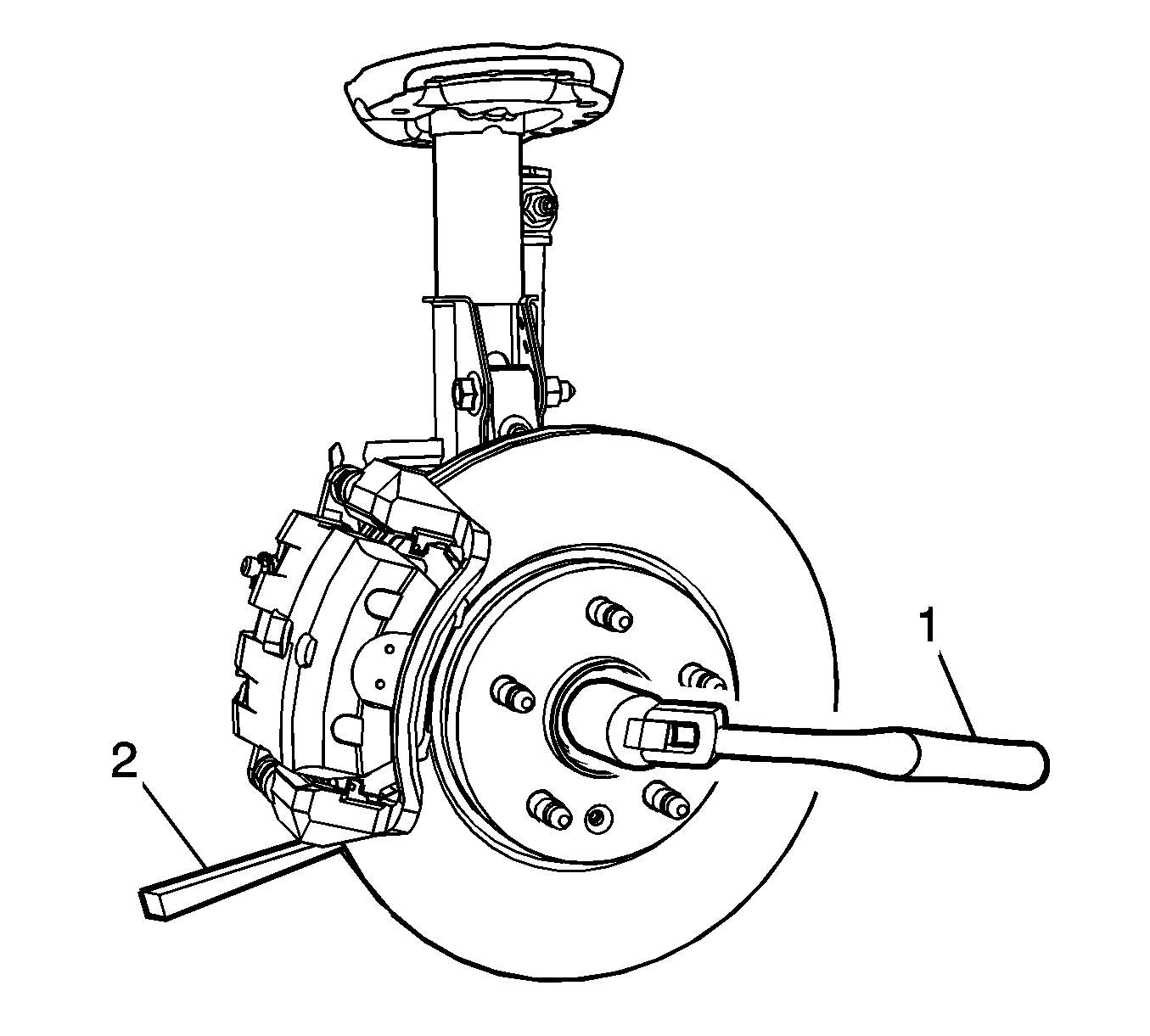 Courtesy of GENERAL MOTORS COMPANY
- Rotate the brake rotor until the drift or punch contacts the brake caliper mounting bracket.
- Using a torque wrench (1) and the appropriate size socket, tighten the wheel drive shaft nut to 150 N.m (111 lb ft).
- Release the wheel drive shaft nut trough 45 degrees.
- Retighten the wheel drive shaft nut to 250 N.m (185 lb ft).
- Install the tire and wheel assembly. Refer to Tire and Wheel Removal and Installation
.
- Lower the vehicle.