Control Solenoid Valve and Transmission Control Module Assembly Input Shaft Speed/Output Shaft Speed Input Test
Control Solenoid Valve and Transmission Control Module Assembly Input Shaft Speed/Output Shaft Speed Input Test
Special Tools
* DT-47825-10 - Jumper Harness
* J 35616 - GM-Approved Terminal Test Kit
* J 38522 - Variable Signal Generator
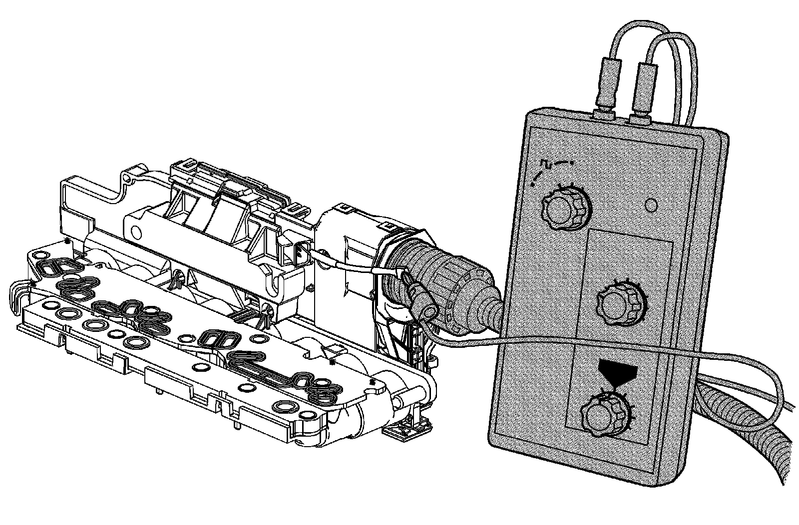
The purpose of this test is to provide a simulated input/output speed sensor (ISS/OSS) signal to the control solenoid valve assembly ISS/OSS input circuits.
Transmission Input Speed Sensor
1. Ignition OFF, connect the DT-47825-10 - jumper harness between the vehicle wire harness electrical connector, and the control solenoid valve assembly electrical connector.
2. Disconnect the ISS/OSS wiring harness connector X3 (1) from the control solenoid valve assembly.
3. Ignition ON, test for 8.3-9.3 volts between the ISS/OSS voltage circuit terminal B on the control solenoid valve assembly and ground at the transmission case.
• If not within the specified range, replace the control solenoid valve assembly. Refer to Control Solenoid Valve and Transmission Control Module Assembly Replacement 6L45/6L50/6L80/6L90 - Automatic Transmission.
4. Using the J 35616 - terminal test kit, connect the J 38522 - variable signal generator red lead to the ISS signal circuit terminal A on the TCM.
5. Connect the black lead from the J 38522 - variable signal generator to ground at the transmission case.
6. Set the J 38522 - variable signal generator to 5 volts, the frequency to 300, and the percent duty cycle to 50 or the normal position.
7. Ignition ON, verify with a scan tool the Transmission ISS parameter is between 760-785 RPM.
• If not within the specified range, replace the control solenoid valve assembly. Refer to Control Solenoid Valve and Transmission Control Module Assembly Replacement 6L45/6L50/6L80/6L90 - Automatic Transmission.
Transmission Output Speed Sensor
1. Ignition OFF, connect the DT-47825-10 - jumper harness between the vehicle wire harness electrical connector, and the control solenoid valve assembly electrical connector.
2. Disconnect the ISS/OSS wiring harness connector X3 (1) from the control solenoid valve assembly.
3. Ignition ON, test for 8.3-9.3 volts between the ISS/OSS voltage circuit terminal B on the control solenoid valve assembly and ground at the transmission case.
• If not within the specified range, replace the control solenoid valve assembly. Refer to Control Solenoid Valve and Transmission Control Module Assembly Replacement 6L45/6L50/6L80/6L90 - Automatic Transmission.
4. Using the J 35616 - terminal test kit, connect the J 38522 - variable signal generator red lead to the OSS signal circuit terminal C on the TCM.
5. Connect the black lead from the J 38522 - variable signal generator to ground at the transmission case.
6. Set the J 38522 - variable signal generator to 5 volts, the frequency to 300, and the percent duty cycle to 50 or the normal position.
7. Ignition ON, verify with a scan tool the Transmission OSS parameter is between 495-505 RPM.
• If not within the specified range, replace the control solenoid valve assembly. Refer to Control Solenoid Valve and Transmission Control Module Assembly Replacement 6L45/6L50/6L80/6L90 - Automatic Transmission.