Steering Linkage Outer Tie Rod Replacement
Steering Linkage Outer Tie Rod Replacement (L99, LFX, LS3, N41)
Special Tools
J-42188-B - Ball Joint Separator
For equivalent regional tools, refer to Special Tools Tools and Equipment.
Removal Procedure
1. Raise and support the vehicle. Refer to Lifting and Jacking the Vehicle Service and Repair.
2. Remove the front tire and wheel assembly. Refer to Tire and Wheel Removal and Installation (w RT2) Tire and Wheel Removal and Installation (w RT2)Tire and Wheel Removal and Installation (w/o RT2) Tire and Wheel Removal and Installation (w/o RT2).
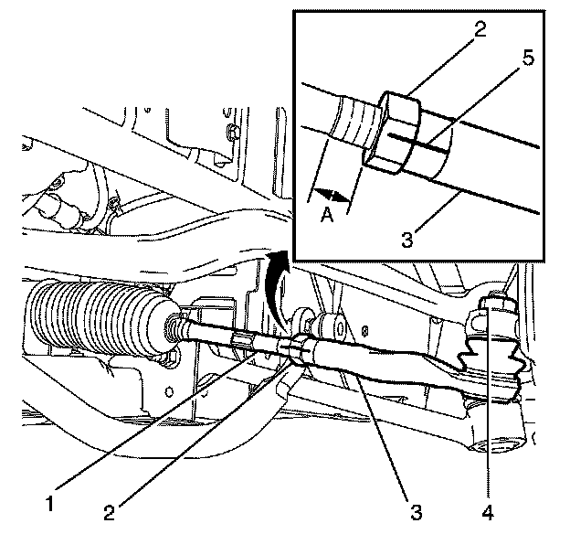
3. Use paint in order to place match marks (5) on the steering linkage inner tie rod nut (2) and on the steering linkage outer tie rod (3).
4. Measure and record the distance of the thread (A) in relation to the inner tie rod nut.
5. Loosen the inner tie rod nut half a turn.
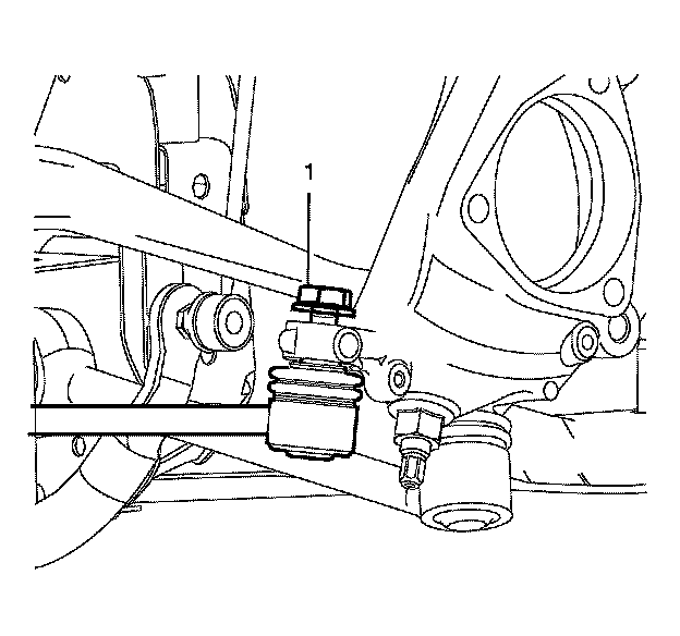
6. Loosen the outer tie rod nut (1) to the top of the stud.
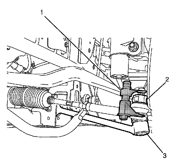
7. Use the J-42188-B - separator (1) in order to disengage the outer tie rod from the steering knuckle (2).
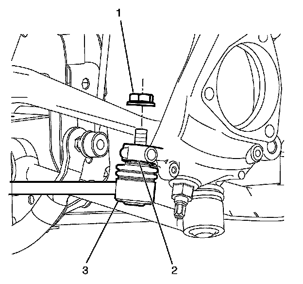
8. Remove and discard the outer tie rod nut (1).
9. Separate the outer tie rod (3) from the steering knuckle (2).
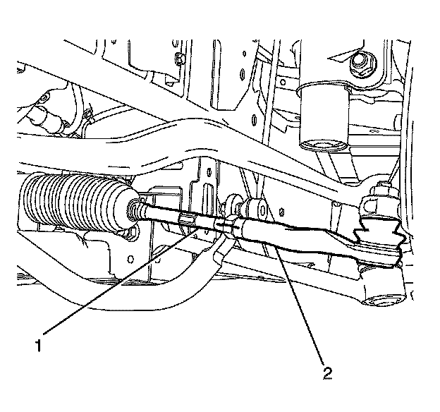
10. Remove the outer tie rod (2) from the inner tie rod (1). Count and record the number of turns necessary in order to remove the outer tie rod.
Installation Procedure
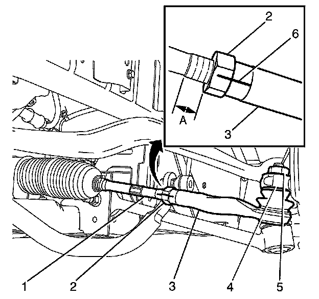
1. Install the outer tie rod (3) to the inner tie rod (1). Use the same number of turns as recorded during the removal procedure.
Note:
Do not tighten the inner tie rod nut (2) yet.
2. Ensure the distance (A) is the same as recorded during the removal procedure.
3. Connect the outer tie rod to the steering knuckle (4).
Caution:
Refer to Fastener Caution Fastener Caution.
4. Install the NEW outer tie rod nut (5) and tighten to 30 Nm (22 lb ft).
5. Tighten the outer tie rod nut an additional 120 degrees.
6. Align the match marks (6).
7. Install the front tire and wheel assembly. Refer to Tire and Wheel Removal and Installation (w RT2) Tire and Wheel Removal and Installation (w RT2)Tire and Wheel Removal and Installation (w/o RT2) Tire and Wheel Removal and Installation (w/o RT2).
8. Measure and adjust the front toe. refer to Wheel Alignment - Steering Wheel Angle and/or Front Toe Adjustment Wheel Alignment - Steering Wheel Angle and/or Front Toe Adjustment.
9. Tighten the inner tie rod nut to 75 Nm (55 lb ft).
10. Lower the vehicle.