Drive Sprocket and Turbine Shaft Assemble: Assembly
 Courtesy of GENERAL MOTORS CORP.
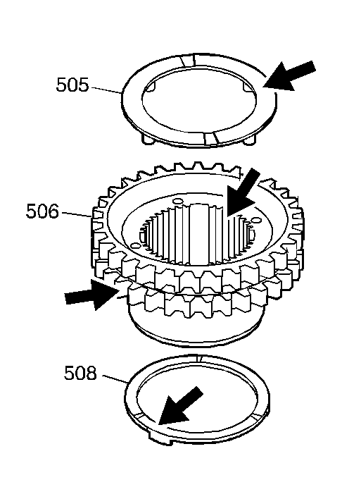
- Inspect the driven sprocket (506) for the following:
- Worn or chipped teeth
- Uniform teeth size
- Stripped or damaged splines
- Bearing surface damage
- Inspect the fourth clutch shaft thrust washer (505) and the driven sprocket thrust washer (508) for wear or cracks.
 Courtesy of GENERAL MOTORS CORP.
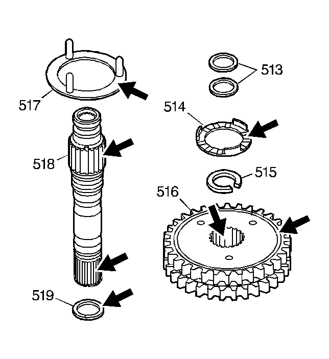
- Inspect the drive sprocket (516) for the following:
- Worn or chipped teeth
- Uniform teeth size
- Stripped or damaged splines
- Bearing surface damage
- Inspect the turbine shaft (518) for the following:
- A cracked sleeve
- Damaged bushing journals
- Stripped or damaged splines
- Inspect the drive sprocket thrust washers (514, 517) for wear or cracks.
 Courtesy of GENERAL MOTORS CORP.
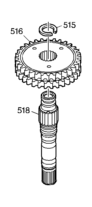
- Insert the turbine shaft (518) into the drive sprocket (516) and attach the drive sprocket retaining ring (515).
 Courtesy of GENERAL MOTORS CORP.
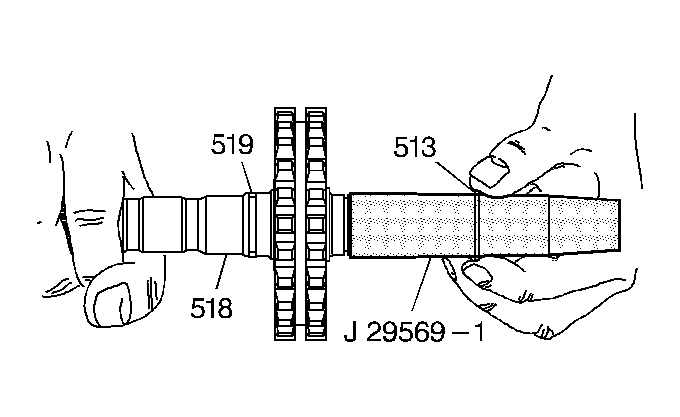
- Install J 29569-1:
seal installer expander onto the turbine shaft (518). Coat the tool shaft with J 36850:
lubricant or equivalent.
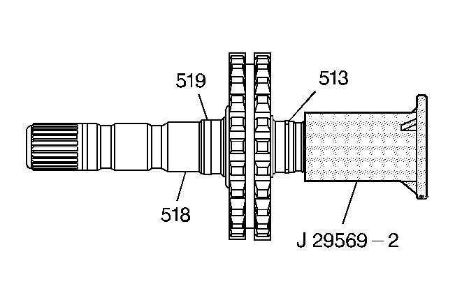
- Slide the turbine shaft oil seal rings (513) into position.
 Courtesy of GENERAL MOTORS CORP.
- Use J 29569-2:
seal installer compressor in order to size the turbine shaft oil seal rings (513).
 Courtesy of GENERAL MOTORS CORP.
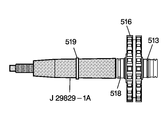
- Install J 29829-1A:
seal installer expander onto the turbine shaft (518). Coat the tool shaft with J 36850:
lubricant or equivalent.
- Slide the turbine shaft oil seal ring (519) into position.
 Courtesy of GENERAL MOTORS CORP.
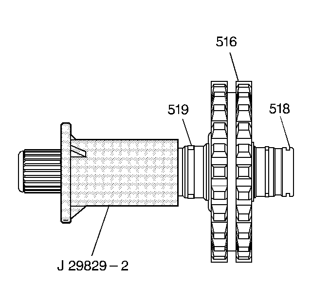
- Use J 29829-2:
seal installer compressor in order to size the turbine shaft oil seal ring (519).