Transmission Oil Pump Cover Assemble
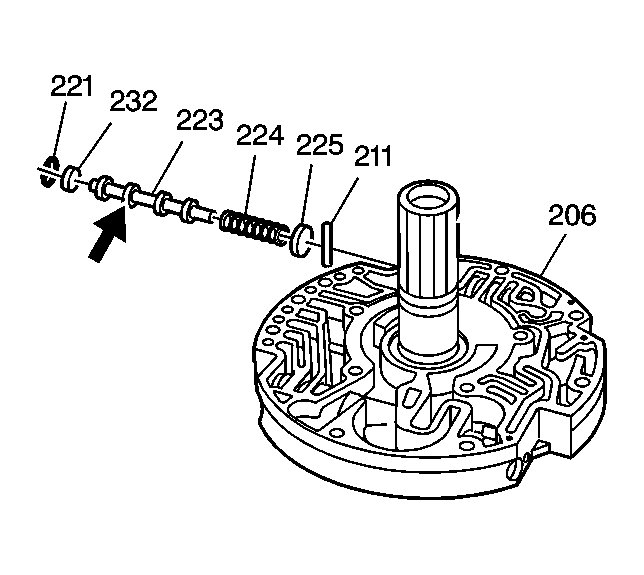 Courtesy of GENERAL MOTORS CORP.
- Install the TCC shift valve spring seat pin (211) into the oil pump cover (206).
- Install the TCC shift valve spring seat (225).
- Install the TCC shift valve spring (224).
- Install the TCC shift valve (223).
- Install the pressure regulator (TCC shift) valve bore plug (232).
- Install the TCC shift valve bore plug retainer ring (221).
- Inspect the TCC shift valve (223) for free movement in the bore.
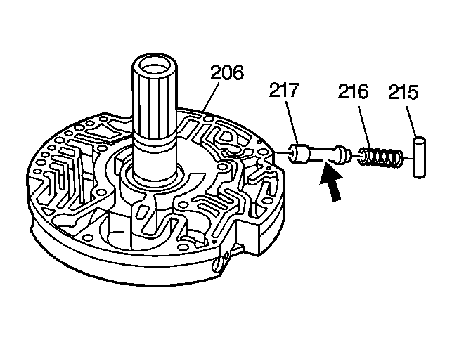 Courtesy of GENERAL MOTORS CORP.
- Install the TCC enable valve (217) into the oil pump cover (206).
- Install the TCC enable valve spring (216).
- Compress the TCC enable valve spring (216), and insert a small rod into the fluid passage in order to retain the TCC enable valve spring.
- Install the TCC enable valve spring retainer sleeve (215).
- Remove the small rod.
- Inspect the TCC enable valve (217) for free movement in the bore.
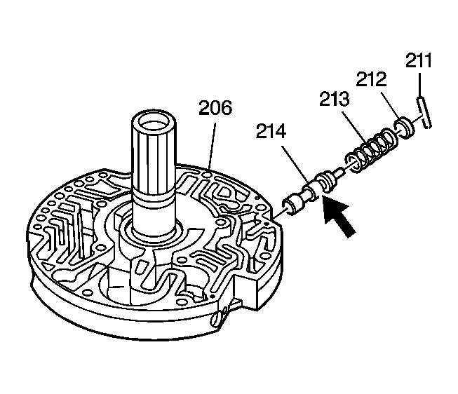 Courtesy of GENERAL MOTORS CORP.
- Install the converter regulator valve (214) into the oil pump cover (206).
- Install the converter regulator valve spring (213).
- Install the converter regulator valve bore plug (212).
- Install the converter regulator valve bore plug pin (211).
- Inspect the converter regulator valve (214) for free movement in the bore.
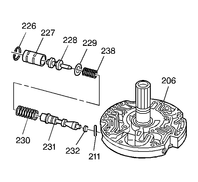 Courtesy of GENERAL MOTORS CORP.
- Install the pressure regulator valve bore plug pin (211) into the oil pump cover (206).
- Install the pressure regulator valve bore plug (232).
- Install the pressure regulator valve (231).
- Install the pressure regulator valve inner (238) and outer (230) springs.
- Install the pressure regulator valve spring retainer (229).
- Assemble the reverse boost valve (228) into the reverse boost valve bushing (227) with the reverse boost valve stem facing out of the bushing.
- Install the reverse boost valve assembly (227, 228).
- Install the reverse boost valve bushing retainer ring (226).