Test F: Speedometer/Odometer Inaccurate Or Inoperative: Testing
- If diagnostic system check has been performed, go to next step. If diagnostic system check has not been performed, perform INSTRUMENT CLUSTER DIAGNOSTIC SYSTEM CHECK under SELF-DIAGNOSTIC SYSTEM.
- Connect scan tool to Data Link Connector (DLC). DLC is located below left side of instrument panel, to right of steering column. Raise and support vehicle's drive wheels. Start engine and place transmission into Drive (automatic transmission) or 3rd gear (manual transmission). Using scan tool, observe Vehicle Speed Sensor (VSS) parameter in Powertrain Control Module (PCM) for 2001, or Instrument Panel Cluster (IPC) for 2002 engine data 1 data list. See SCAN TOOL DATA LIST table. If VSS parameter matches speedometer display, go to next step. If VSS parameter does not match speedometer display, go to step 4.
- If odometer does not operate correctly, go to step 8. If odometer operates correctly, inspect for intermittents or poor connections. See TROUBLE SHOOTING .
- Turn ignition switch to OFF position. Disconnect PCM 80-pin harness connector. PCM is located on right side of engine compartment, near rear of wheelwell. Start engine and place transmission into Drive (automatic transmission) or 3rd gear (manual transmission). Measure voltage of Dark Green/White wire between ground and PCM harness connector C1 terminal No. 55 (3.8L) or PCM harness connector C2 terminal No. 50 (5.7L). See Fig 1. If voltage is less than 9.6 volts, go to next step. If voltage is 9.6 volts or more, go to step 6.
- Inspect Dark Green/White wire for an open or high resistance between PCM harness connector C1 terminal No. 55 (3.8L) or PCM harness connector C2 terminal No. 50 (5.7L) and Instrument Panel Cluster (IPC) harness connector terminal B8. See Fig 1 and Fig 2
. If an open or high resistance is not found, go to step 8. If an open or high resistance is found, repair as necessary then go to step 11.
- Inspect Dark Green/White wire for a short to battery voltage between the IPC and the PCM. If no condition was found, go to next step. If condition was found, repair as necessary and go to step 11.
- Inspect PCM harness connector for poor connections. If poor connections are not found, go to step 9. If poor connections are found, repair as necessary then go to step 11.
- Inspect IPC harness connector for poor connections. If poor connections are not found, go to step 10. If poor connections are found, repair as necessary then go to step 11.
- Replace PCM. Program PCM. See POWERTRAIN CONTROL MODULE under PROGRAMMING. After replacement, go to step 11.
- Replace IPC. Program IPC. See INSTRUMENT PANEL CLUSTER under PROGRAMMING. After replacement, go to next step .
- Operate system to verify repair. If condition has been corrected, system is operating correctly at this time. If condition has not been corrected, repeat test procedure beginning at step 2.
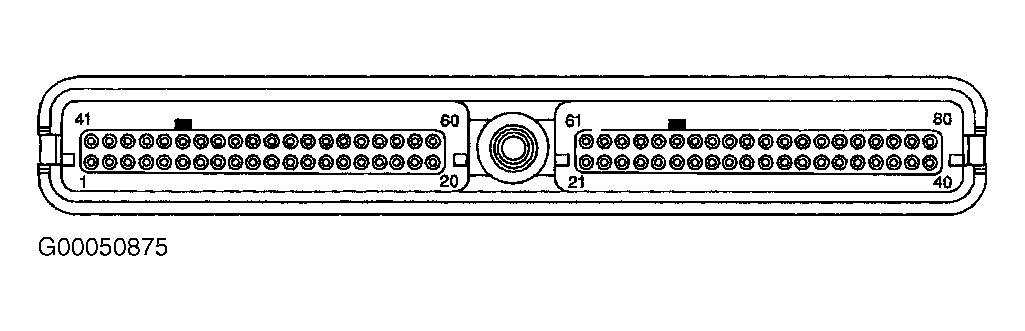 Courtesy of GENERAL MOTORS CORP.
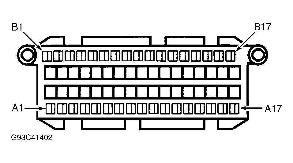 Courtesy of GENERAL MOTORS CORP.