TCC PWM Solenoid, TCC Solenoid & Wiring Harness: Installation
- Install the wiring harness and TCC solenoid assembly with a new O-ring seal to the transmission. Install the pass-through electrical connector to the transmission case. See Fig 4.
- Install the valve body bolts which retain the internal wiring harness and install the TCC solenoid retaining bolts. See Fig 3. Tighten the control valve body retaining bolts to specification. See TORQUE SPECIFICATIONS .
- Tighten the TCC solenoid retaining bolts to specification. See TORQUE SPECIFICATIONS .
- Install the pressure control solenoid. See Figure. Ensure the electrical tabs are facing outboard. Install the pressure control solenoid retainer and retaining bolt. Tighten the pressure control solenoid retaining bolt to specification. See TORQUE SPECIFICATIONS .
- Install the TCC PWM solenoid to the control valve body. See Fig 2. Install the TCC PWM solenoid retainer.
- Connect the internal wiring harness electrical connectors to the following components: Transmission fluid pressure switch (1), 1-2 shift control solenoid (2), 2-3 shift control solenoid (3), pressure control solenoid (4), TCC PWM solenoid (5), and the 3-2 control solenoid (6). Install the 1-2 accumulator. See Figure.
- Connect the transmission harness 20-way connector to the transmission pass-through connector. Align the arrows on each half of the connector and insert straight down. See Fig 1.
- Install the transmission oil pan and filter. See DRAINING & REFILLING under LUBRICATION. Lower the vehicle. Fill transmission with appropriate fluid to proper level. See LUBRICATION .
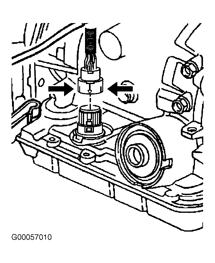 Courtesy of GENERAL MOTORS CORP.
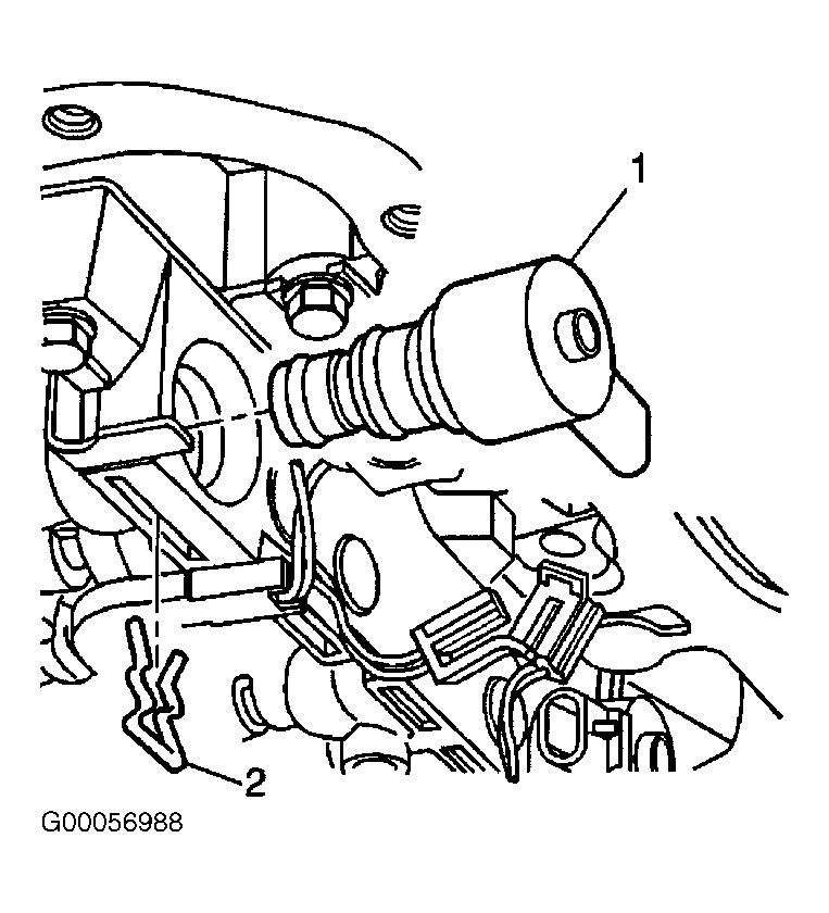 Courtesy of GENERAL MOTORS CORP.
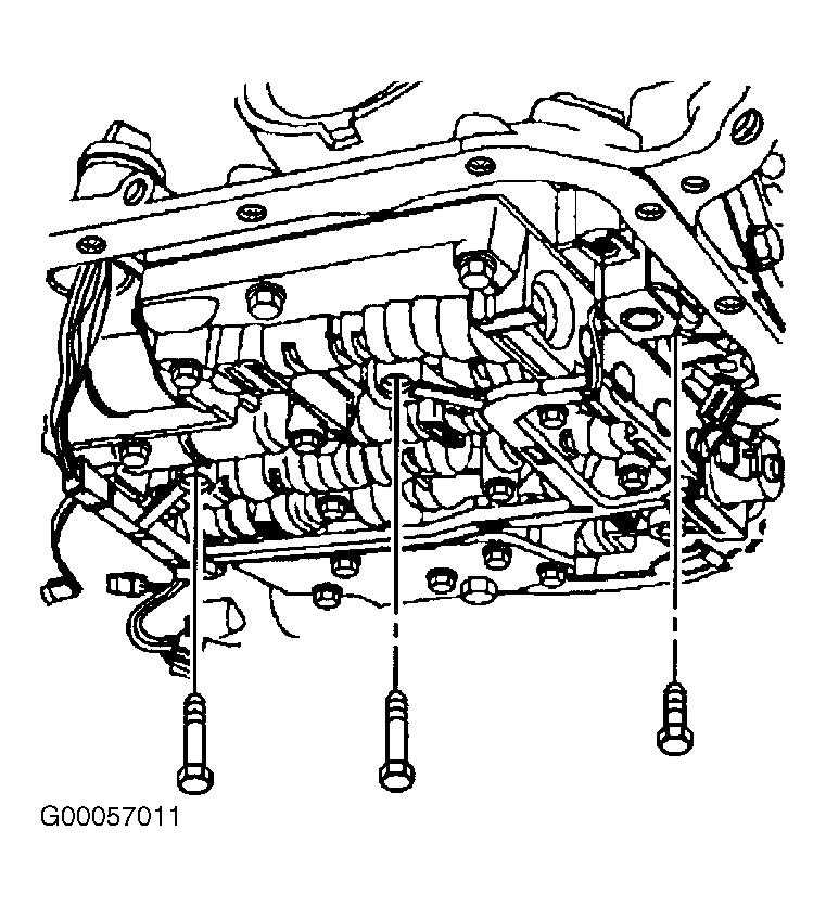 Courtesy of GENERAL MOTORS CORP.
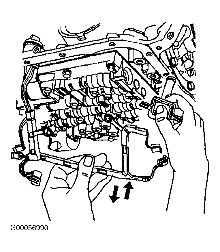 Courtesy of GENERAL MOTORS CORP.
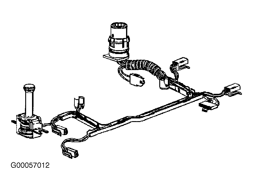 Courtesy of GENERAL MOTORS CORP.