Component Resistance
Connect DVOM between specified terminals at component or at transmission in-line 20-pin connector to transmission. Measure individual component resistance at specified temperature. See Fig 1. See COMPONENT RESISTANCE SPECIFICATIONS table. If resistance is not as specified, replace appropriate component.
COMPONENT RESISTANCE SPECIFICATIONS
| Component |
Pins |
Ohms |
Ohms |
Resistance To Ground (Case) |
| Pressure Control Solenoid |
C & D |
3-5 |
4-7 |
|
| Speed Sensor |
A & B |
1377-2220 |
1800-3355 |
|
| TCC PWM Solenoid |
U & E |
10-11 |
13-15 |
|
| TCC Solenoid Valve |
T & E |
21-26 |
26-33 |
|
| TFT Sensor |
L & M |
3088-3942 |
159-198 |
|
| 1-2 Shift Solenoid |
A & E |
19-24 |
24-31 |
|
| 2-3 Shift Solenoid |
B & E |
19-24 |
24-31 |
|
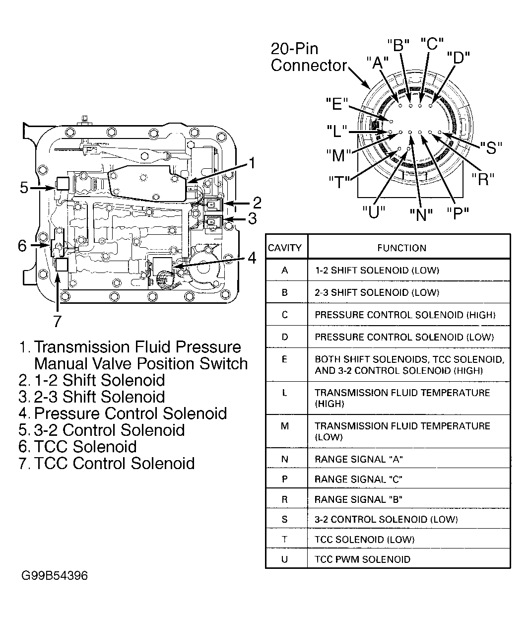 Courtesy of GENERAL MOTORS CORP.
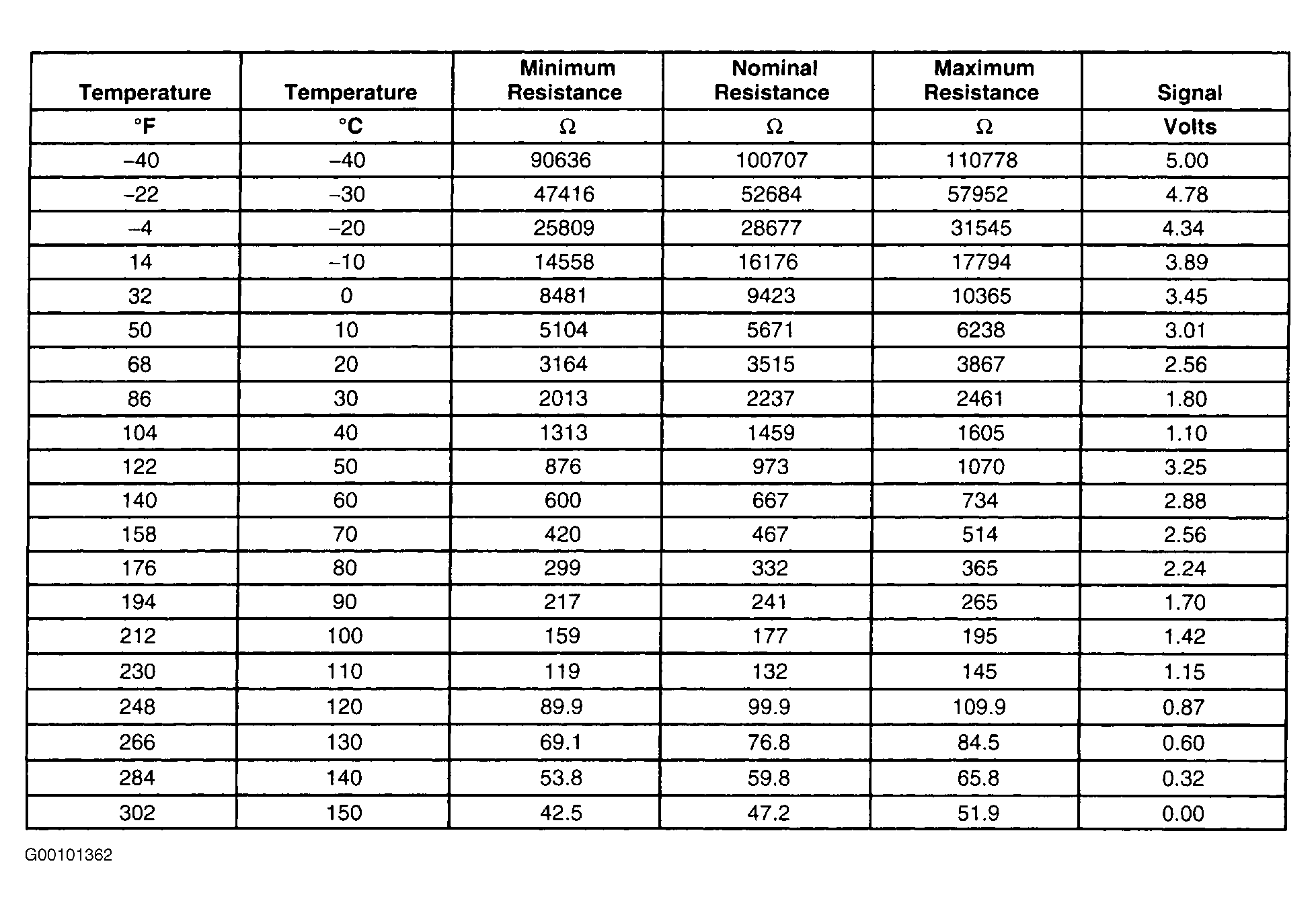 Courtesy of GENERAL MOTORS CORP.