Removal Procedure
- Raise the front of the vehicle. Refer to LIFTING & JACKING THE VEHICLE
in General Information.
- Support the lower control arm with floor stands.
- Place floor stands under the lower control arms as far outboard as possible (between spring seats and ball joint) to maintain maximum leverage.
- Remove the tire and wheel assembly. Refer to TIRE AND WHEEL REMOVAL AND INSTALLATION
in Tires and Wheels.
- Unload the torsion bar. Refer to Torsion Bar and Support Assembly Replacement .
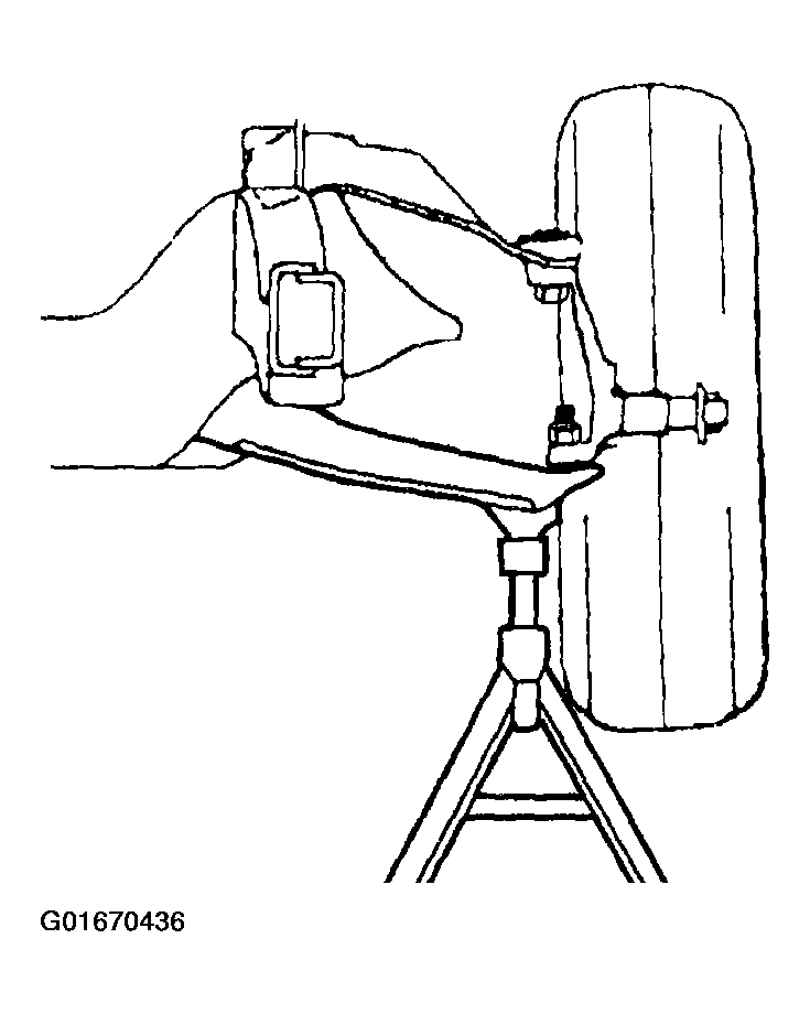 Courtesy of GENERAL MOTORS CORP.
- Remove the shock absorber. Refer to Shock Absorber Replacement (RWD) or Shock Absorber Replacement (4WD) .
- Remove the cotter pin from the upper ball joint stud.
- Remove the upper ball joint retaining nut.
- Using a pry bar, placed under the upper control arm and on top of the frame, pry upward.
- With the aid of a helper, carefully hammer on the steering knuckle in the area of the upper ball joint stud in order to release the stud from the steering knuckle.
- Remove the upper ball joint from the steering knuckle.
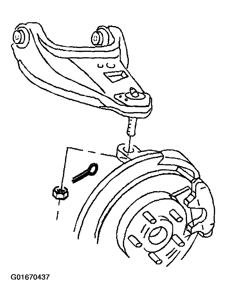 Courtesy of GENERAL MOTORS CORP.
- Remove the upper control arm retaining nuts.
- Remove the upper control arm outer cams.
- Remove the upper control arm bolts.
- Remove the upper control arm inner cams.
- Remove the upper control arm from the frame.
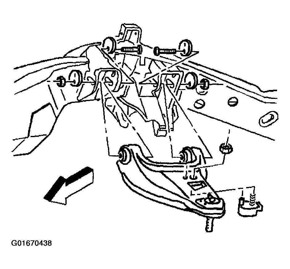 Courtesy of GENERAL MOTORS CORP.
- Remove the upper control arm bumper nut.
- Remove the upper control arm bumper from the upper control arm.
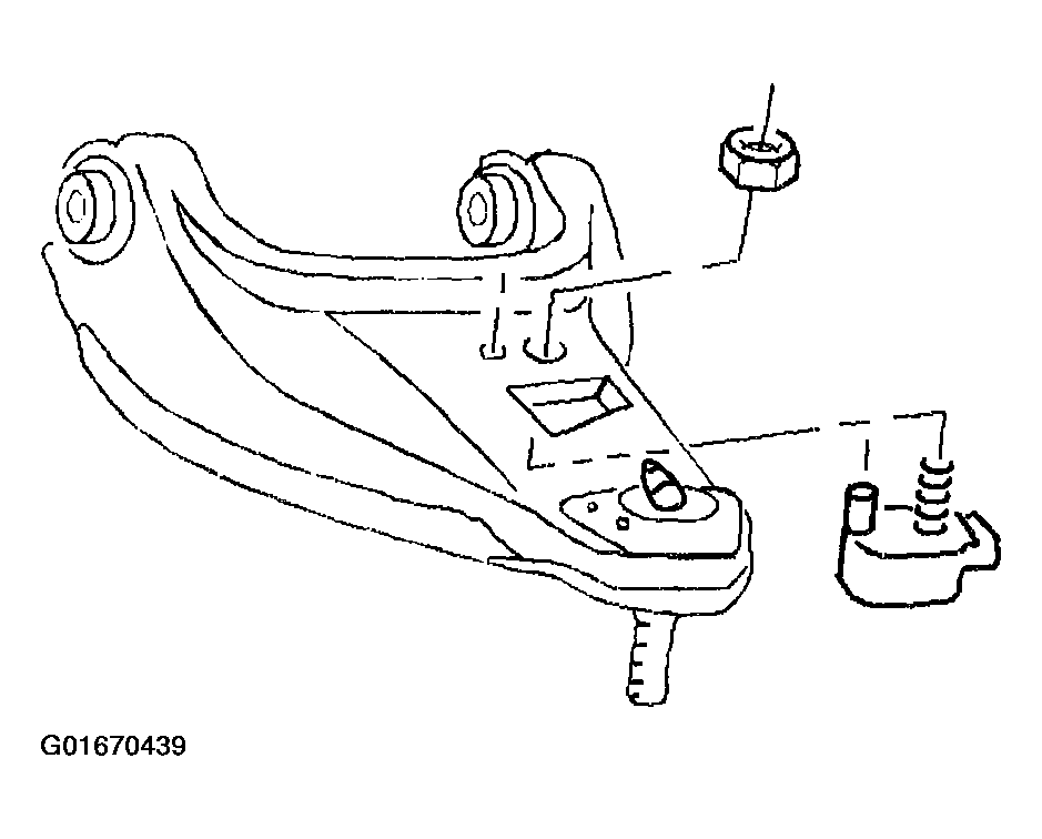 Courtesy of GENERAL MOTORS CORP.