Removal Procedure
- Raise and support the vehicle. Refer to LIFTING & JACKING THE VEHICLE
in General Information.
- Remove the tire and the wheel. Refer to TIRE AND WHEEL REMOVAL AND INSTALLATION
in Tires and Wheels.
- Remove the torsion bar from the lower control arm. Refer to Torsion Bar and Support Assembly Replacement .
- Remove the steering linkage shield. Refer to STEERING LINKAGE SHIELD REPLACEMENT
in Steering Linkage.
 Courtesy of GENERAL MOTORS CORP.
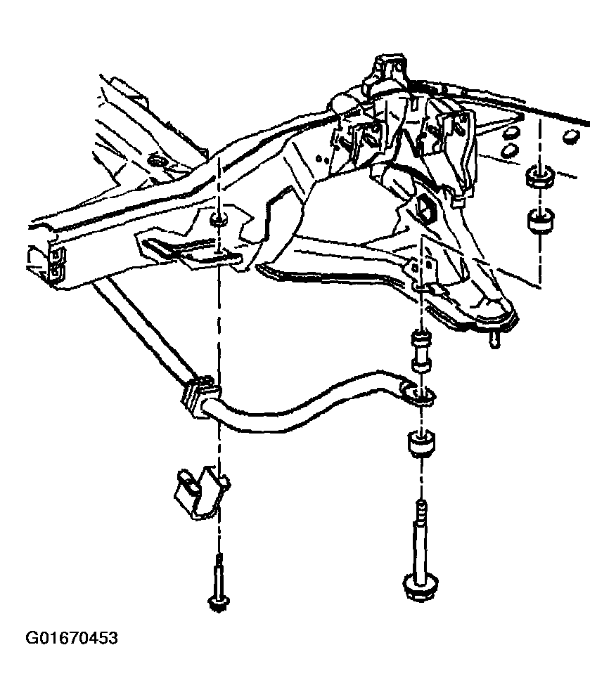
- Remove the stabilizer shaft link from the lower control arm. Refer to Stabilizer Shaft Link Replacement (RWD) or Stabilizer Shaft Link Replacement (4WD) .
- Remove the stabilizer shaft bracket bolts.
- Lower the stabilizer shaft.
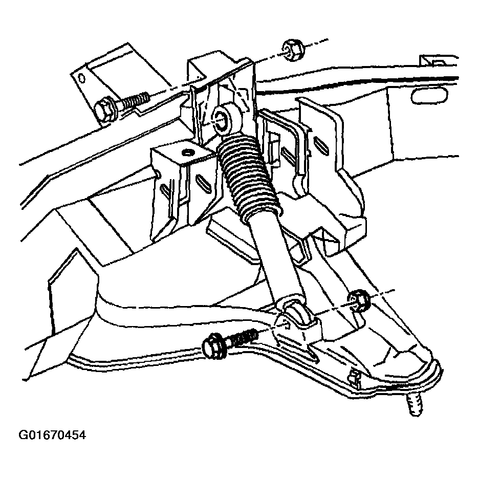
- Remove the shock absorber lower mounting bolt.
- Compress shock absorber.
 Courtesy of GENERAL MOTORS CORP.
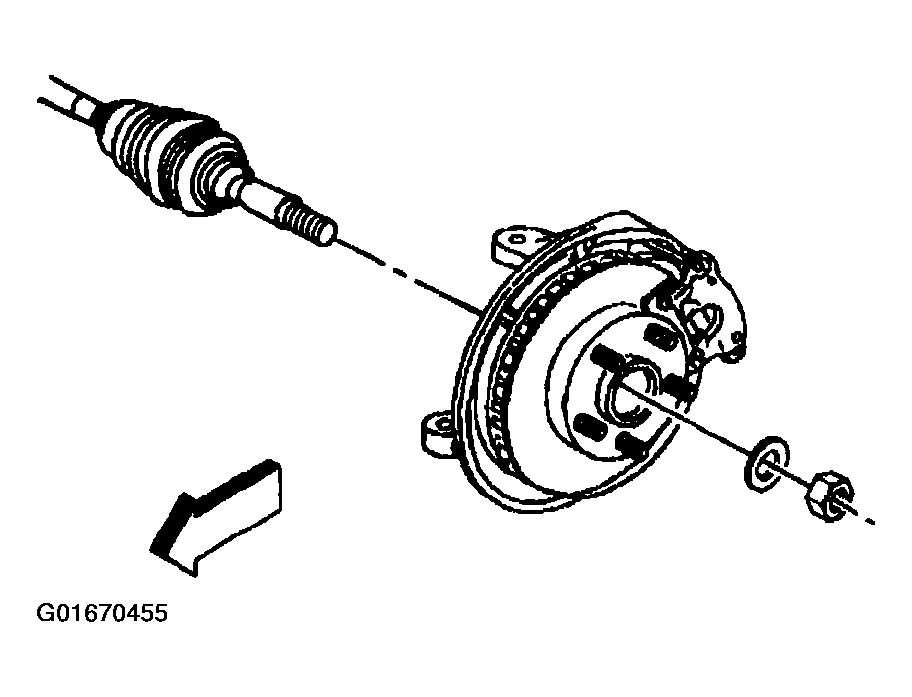
- Remove the wheel drive shaft retaining nut and washer.
 Courtesy of GENERAL MOTORS CORP.
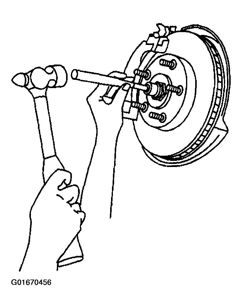
- Disengage the wheel drive shaft from the wheel hub and bearing. Place a brass drift against the outer end of the wheel drive shaft in order to protect the wheel drive shaft threads. Sharply strike the brass drift with a hammer. Do not attempt to remove the wheel drive shaft from the wheel hub and bearing at this time.
- Remove the front brake rotor. Refer to BRAKE ROTOR -- FRONT
in Disc Brakes.
 Courtesy of GENERAL MOTORS CORP.
- Remove the wheel speed sensor wiring harness and brake hose bracket mounting nut and bolt from the upper control arm.
- Remove the wheel speed sensor wiring harness bracket from the frame.
- Disconnect the wheel speed sensor electrical connection.
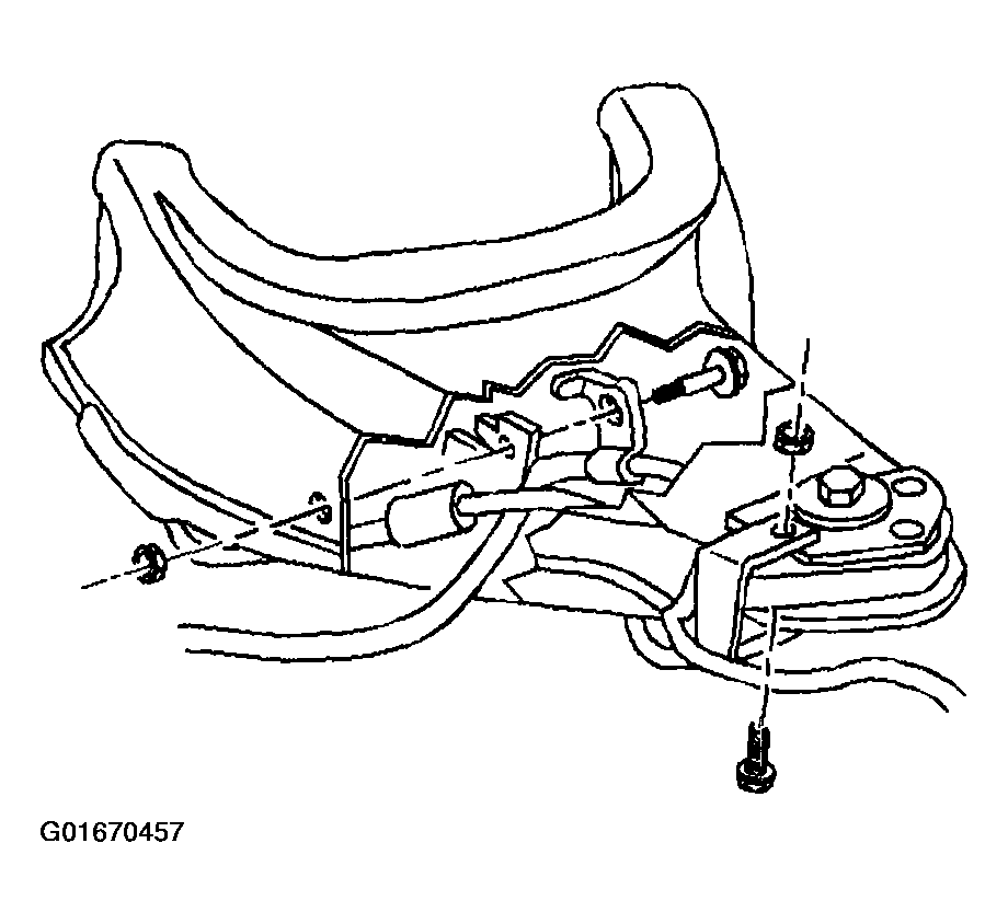 Courtesy of GENERAL MOTORS CORP.
- Remove the outer tie rod cotter pin and retaining nut.
- Remove the outer tie rod from the steering knuckle using J 24319-B
.
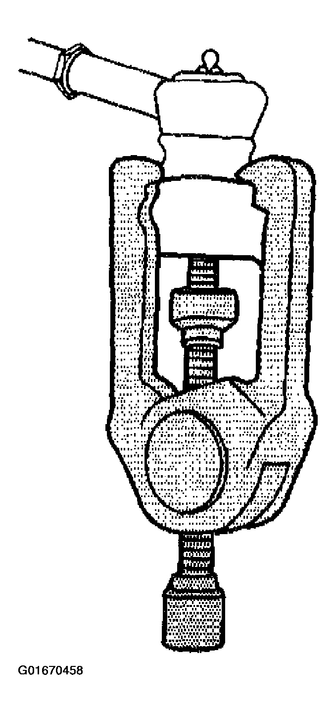 Courtesy of GENERAL MOTORS CORP.
- Remove the upper ball joint cotter pin and retaining nut.
- Using a pry bar, placed under the upper control arm and on top of the frame, pry upward.
- With the aid of a helper, carefully hammer on the steering knuckle in the area of the upper ball joint stud in order to release the stud from the steering knuckle.
- Remove the lower ball joint cotter pin and retaining nut.
- Using J 43631
separate the lower ball joint from the steering knuckle.
- Remove the steering knuckle.
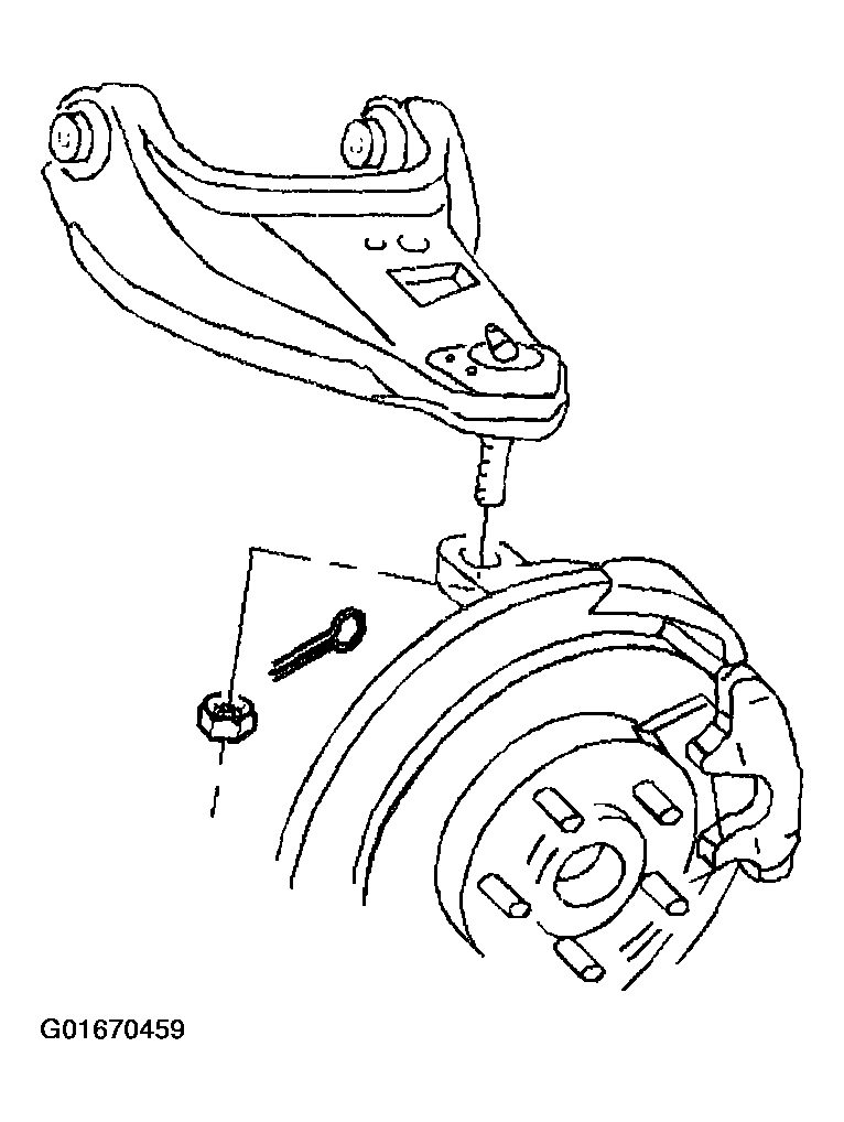 Courtesy of GENERAL MOTORS CORP.
- Remove the lower control arm to the crossmember and the frame bracket mounting nuts and bolts.
- Remove the lower control arm from the frame.
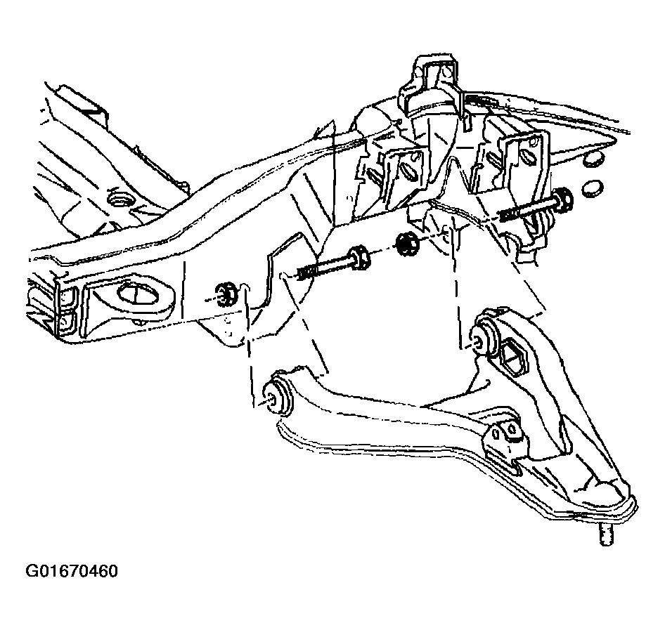 Courtesy of GENERAL MOTORS CORP.