Outer Axle Shafts: Reassembly
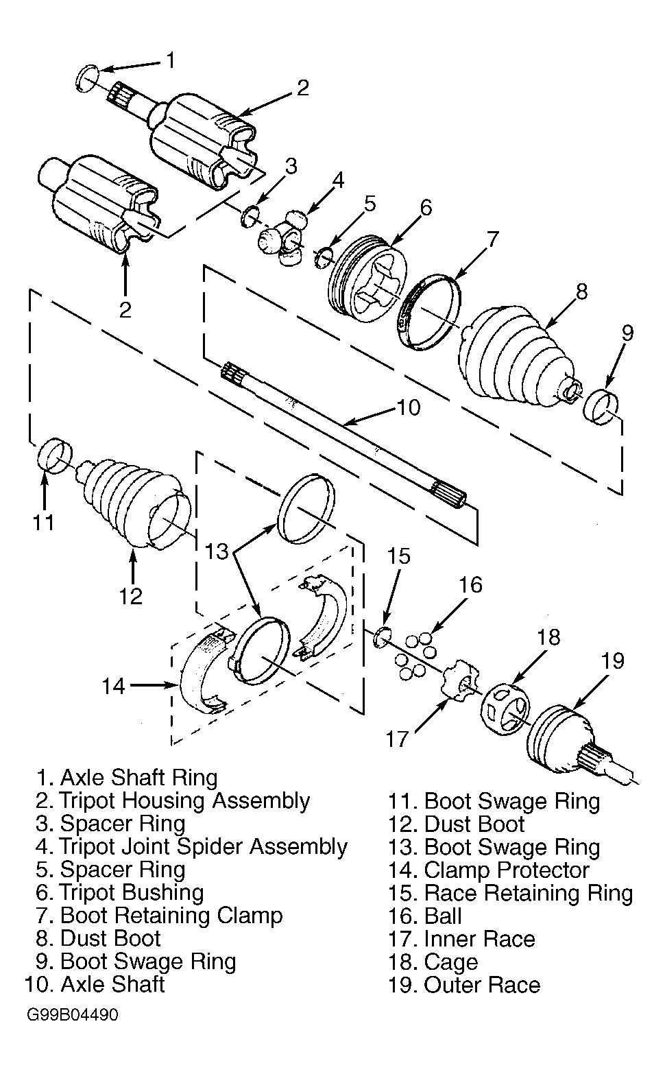
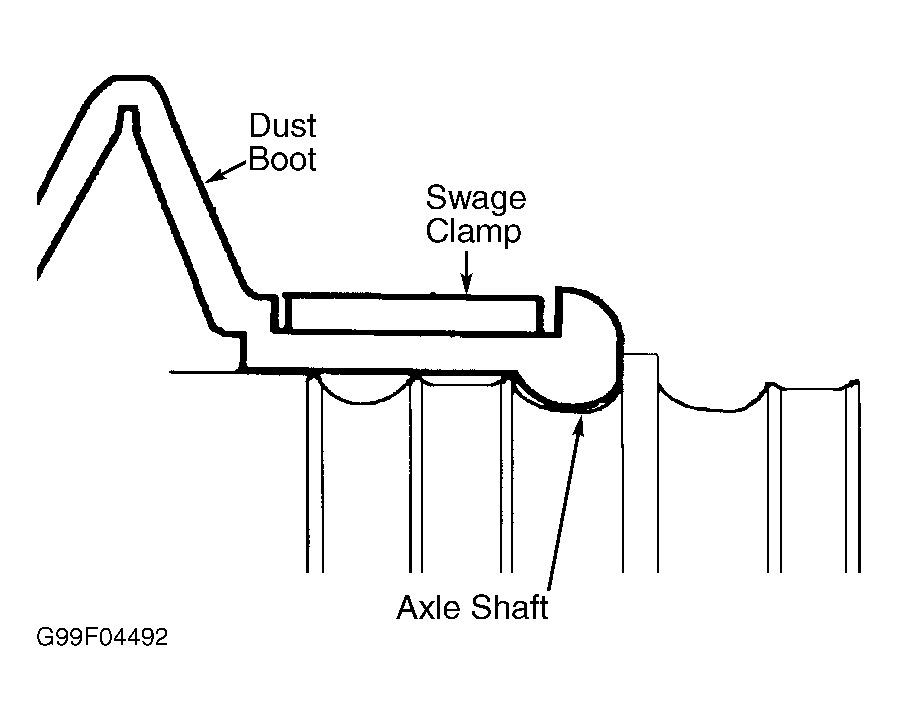
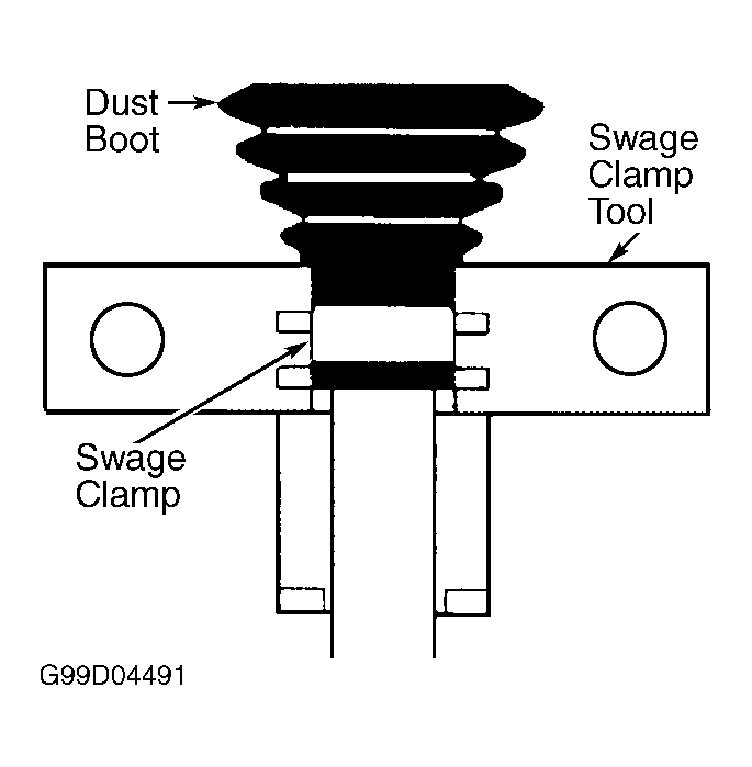
- Slide NEW small swage clamp and dust boot onto axle shaft. See Figure. Place axle shaft in Swage Clamp Installer (J-41048) as illustrated. See Figure. Ensure dust boot is not pinched. Tighten swage clamp installer bolts by hand until snug. Ensure boot, housing and swage clamp are aligned. Tighten each bolt 180-degrees at a time until both sides are bottomed out. Remove swage clamp installer and check swage clamp for deformities. Ensure swage clamp covers entire swaging area. Reswage clamp as necessary. Check swage clamp for any lip deformities.
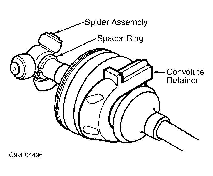
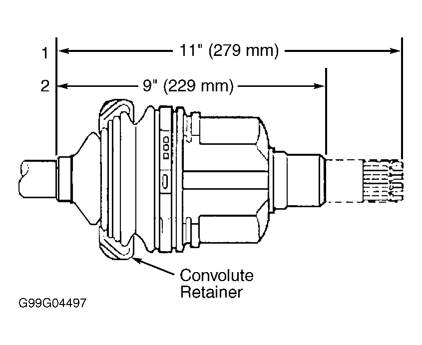
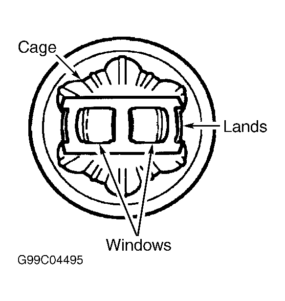
- Install Convolute Retainer (7848076) over dust boot. See Figure. Ensure to capture 4 convolutions. Install spacer rings and spider assembly. Ensure spacer rings are fully seated. Pack boot and housing with pre-measured amount of grease suppled with repair kit. Check inboard stroke position. See Figure. To complete installation, reverse removal procedure.
- Thoroughly degrease all CV joint parts. Check outer CV joint assembly for unusual wear, cracks or other damage. Replace as necessary. Clean any rust at dust boot mounting area. Apply a light coat of grease on inner and outer race grooves. Reassemble CV assembly by reversing removal procedure. Slide NEW small swage clamp and dust boot onto axle shaft. See Fig 2. Place axle shaft in Swage Clamp Installer (J-41048). See Fig 3.
- Ensure dust boot is not pinched. Tighten bolts by hand until snug. Ensure boot, housing and swage clamp are aligned. Tighten each bolt 180 degrees at a time until both sides are bottomed out. Remove swage clamp installer and check swage clamp for deformities. Ensure swage clamp covers entire swaging area. Reswage clamp as necessary. Check swage clamp for any lip deformities.
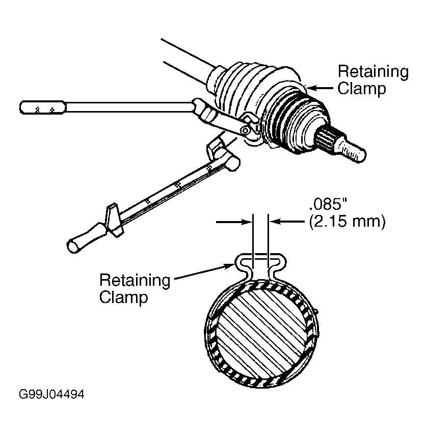
- Install a large retaining ring on dust boot. Pack boot and housing with pre-measured amount of grease suppled with repair kit. Slide CV joint onto axle shaft. An audible click should be heard when retaining snap ring engages. Pull on CV joint to verify engagement. Slide dust boot and retaining ring on to groove on CV joint. Remove any excess air. Secure retaining ring clamp as illustrated. See Fig 7.
 Courtesy of GENERAL MOTORS CORP.
 Courtesy of GENERAL MOTORS CORP.
 Courtesy of GENERAL MOTORS CORP.
 Courtesy of GENERAL MOTORS CORP.
 Courtesy of GENERAL MOTORS CORP.
 Courtesy of GENERAL MOTORS CORP.
 Courtesy of GENERAL MOTORS CORP.