Control Valve Body, Oil Pump & Vehicle Speed Sensor
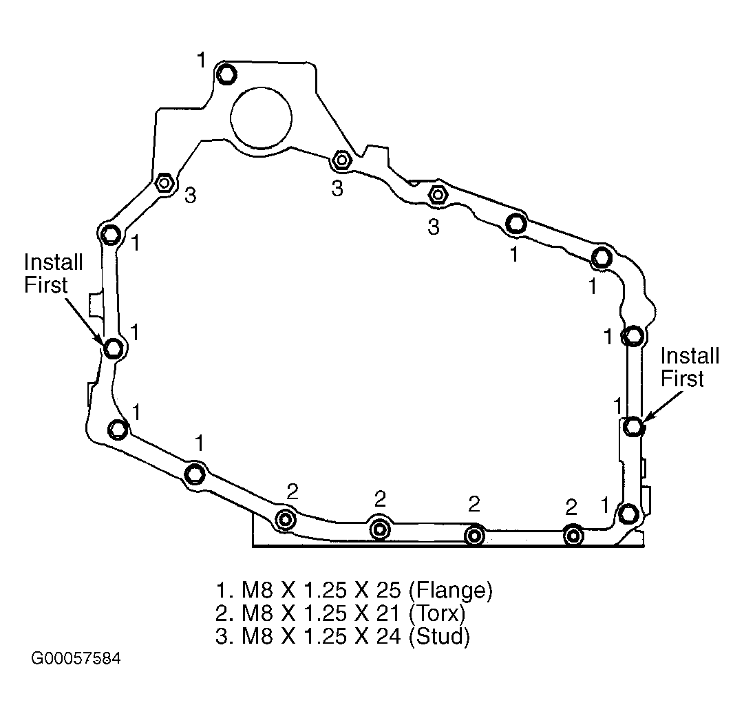
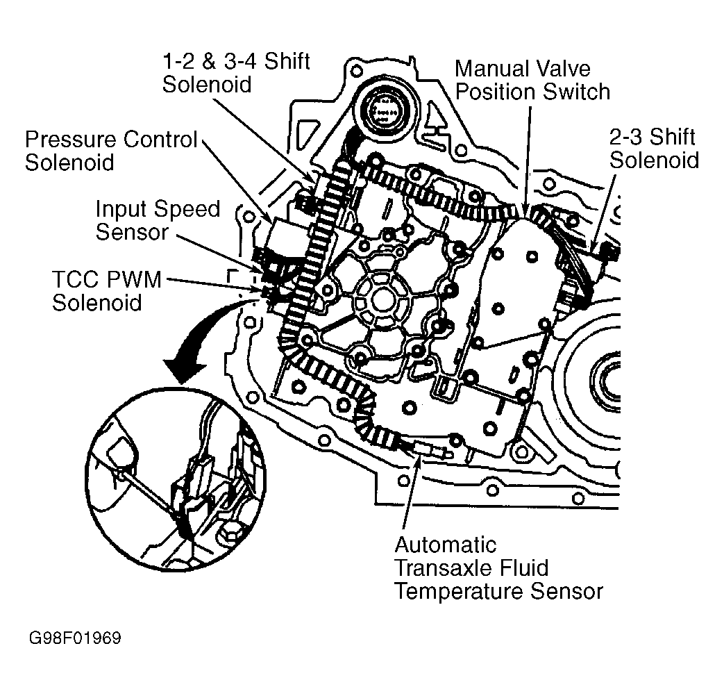
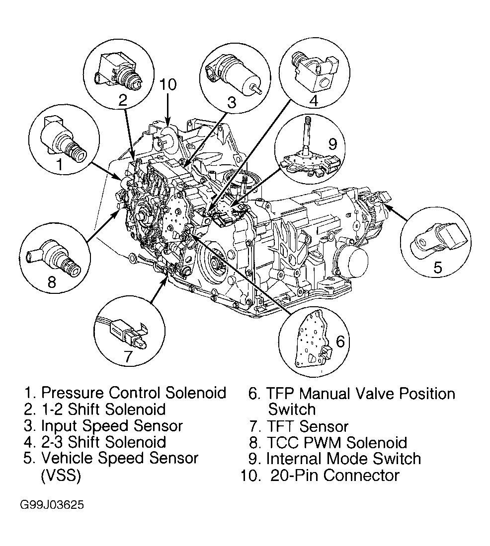
- Position transaxle with control valve body cover facing up. Remove case side cover (control valve body cover) bolts. See Fig 1. Remove cover and gaskets. See Figure. Using small screwdriver, pry wiring harness electrical connectors off transaxle fluid pressure manual valve position switch, 1-2 and 3-4 shift solenoid, 2-3 shift solenoid, TCC PWM solenoid, pressure control solenoid and input speed sensor. Gently pull transaxle fluid temperature sensor from clip. See Fig 2 and Fig 3
.
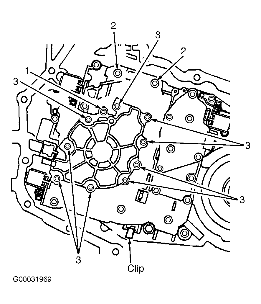
- Lift wiring harness assembly off transaxle. Remove oil pump assembly bolts. DO NOT remove No. 1 oil pump cover bolt at this time. See Fig 4. Remove wiring harness clip. Lift oil pump assembly off control valve body. See Fig 5. Set oil pump assembly on its cover.
- Remove control valve body bolts. See Fig 6. Manual valve position switch is very delicate, use care when handling. Carefully lift manual valve position switch off control valve body. See Fig 7. Remove control valve body. See Fig 8. Remove 4 check balls from case cover. See Fig 9. Remove 2 bolts retaining spacer plate and gaskets to valve body. Remove spacer plate with 2 screen/seal assemblies and gaskets from valve body. Remove 6 check balls from valve body. See Fig 10. Remove case cover pin.
- Remove oil pump drive shaft from case cover. See Fig 11. Position transaxle so Vehicle Speed Sensor (VSS) is facing up. Remove VSS bolt and VSS. See Figure.
 Courtesy of GENERAL MOTORS CORP.
 Courtesy of GENERAL MOTORS CORP.
 Courtesy of GENERAL MOTORS CORP.
 Courtesy of GENERAL MOTORS CORP.
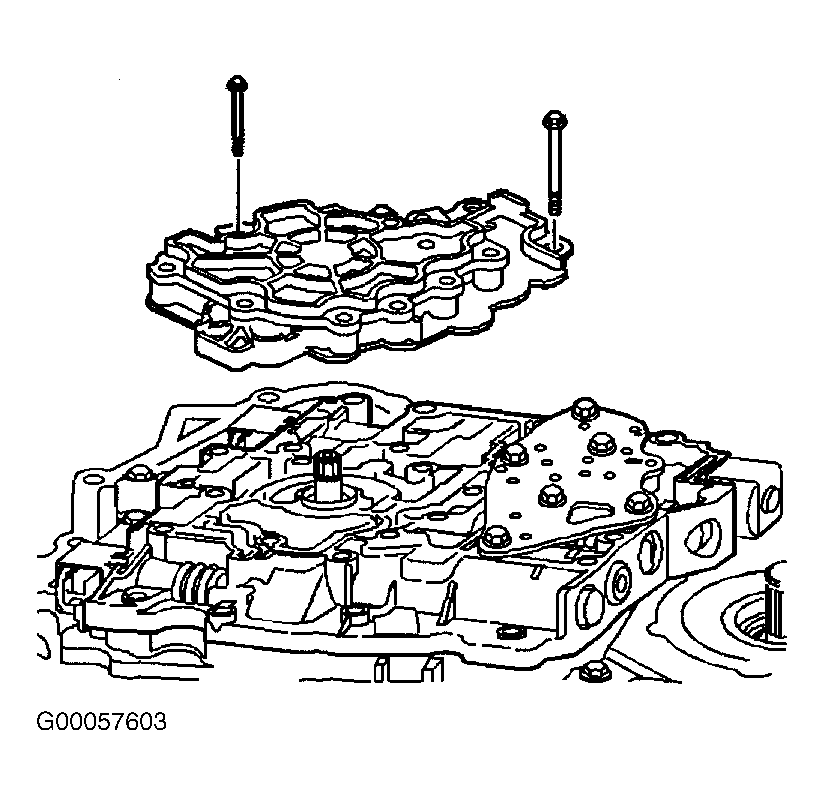 Courtesy of GENERAL MOTORS CORP.
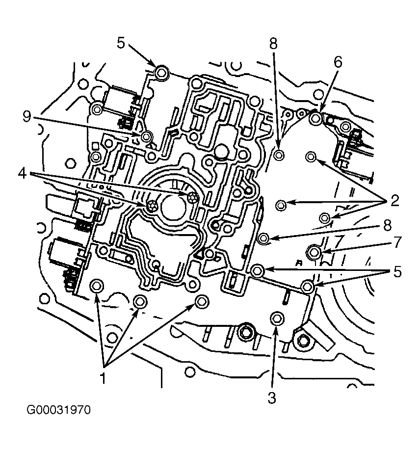 Courtesy of GENERAL MOTORS CORP.
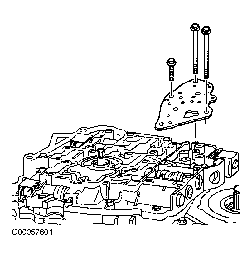 Courtesy of GENERAL MOTORS CORP.
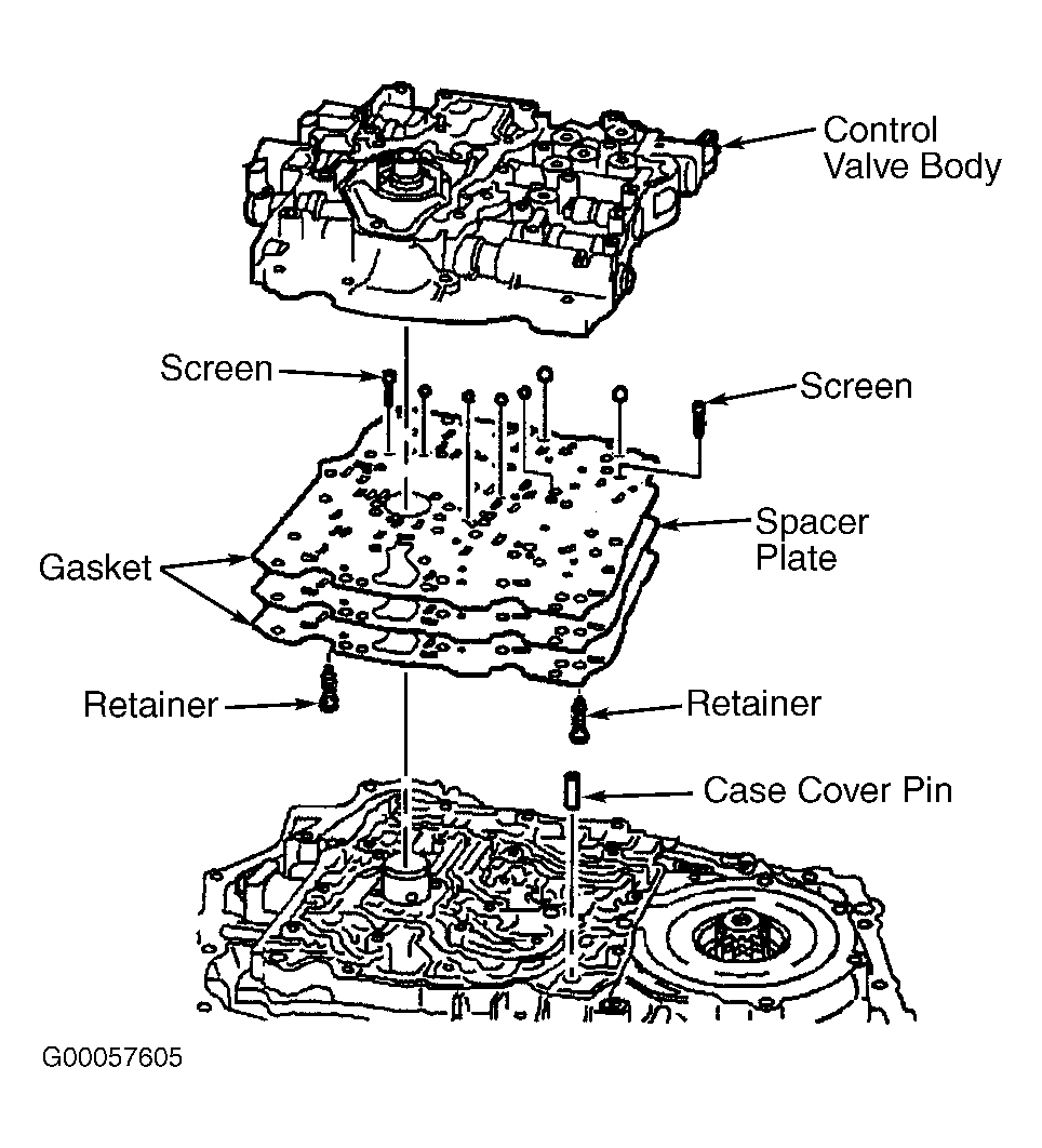 Courtesy of GENERAL MOTORS CORP.
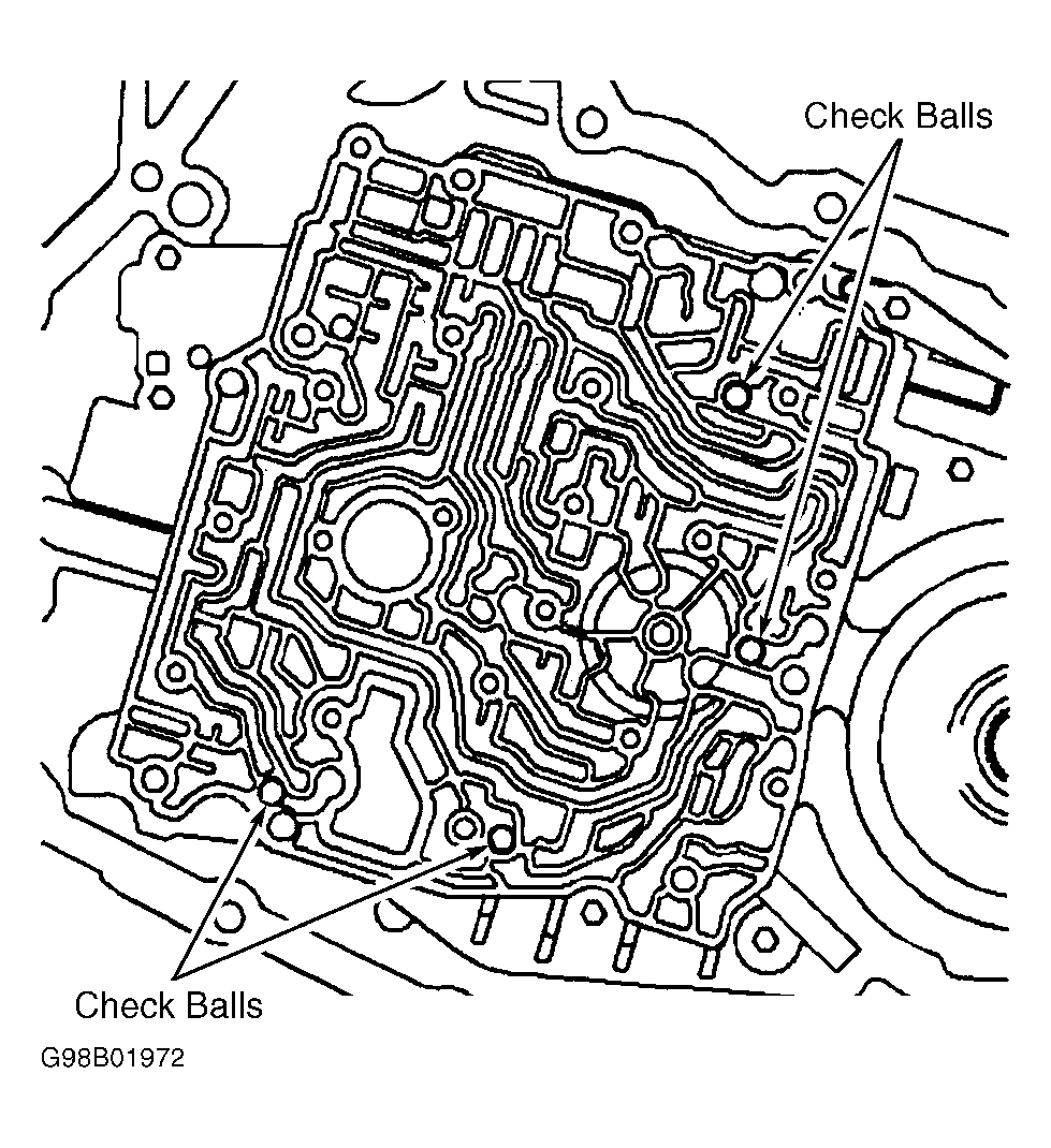 Courtesy of GENERAL MOTORS CORP.
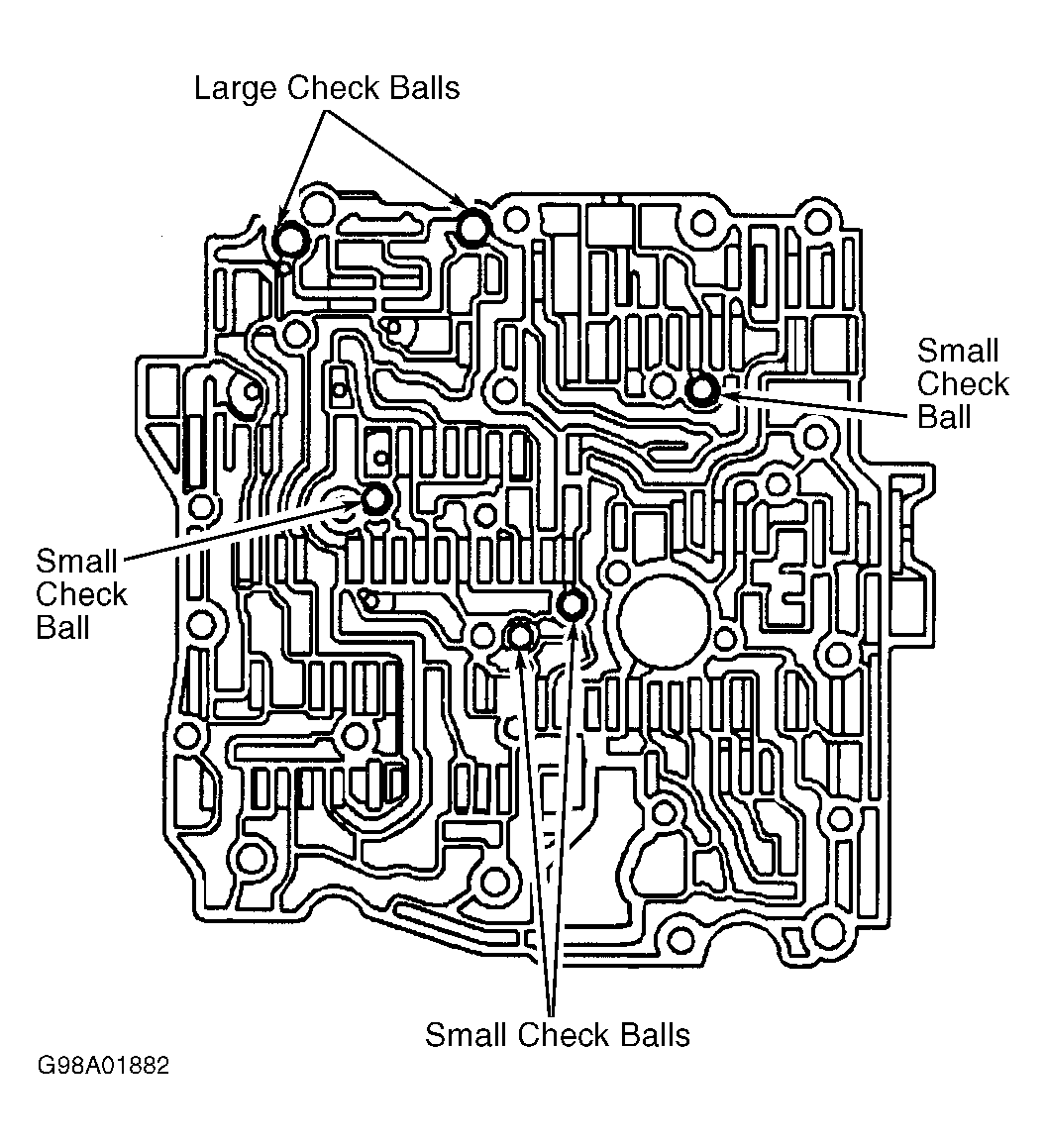 Courtesy of GENERAL MOTORS CORP.
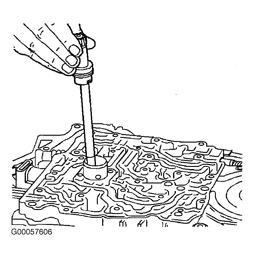 Courtesy of GENERAL MOTORS CORP.