Test A: All Gauges Inoperative
- Turn ignition switch to START position. Check operation of all gauges. If all gauges are inoperative, go to next step. If all gauges are operating normally, check system for intermittent condition. See appropriate BODY CONTROL MODULES article.
- Turn ignition switch to LOCK position. Remove instrument cluster. See INSTRUMENT CLUSTER
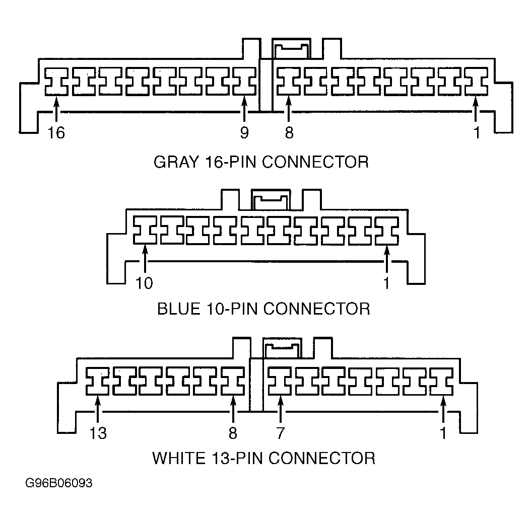
under REMOVAL & INSTALLATION. Disconnect instrument cluster 16-pin harness connector C1. Turn ignition switch to RUN position. Measure voltage between ground and instrument cluster harness connector C1 terminal No. 14 (Black/White wire). See Fig 1
. If battery voltage does not exist, go to next step. If battery voltage exists, go to step 4
.
- Repair short or open in Black/White wire between instrument cluster and instrument panel junction block, and retest system. Instrument panel junction block is located on lower left side of instrument panel.
- Disconnect instrument cluster 13-pin harness connector C3. Check continuity between ground and instrument cluster harness connector C3 terminal No. 2 (Black/Yellow wire). See Fig 1
. If continuity does not exist, go to next step. If continuity exists, go to step 6
.
- Repair open in Black/Yellow wire between instrument cluster and ground. Ground is located on right side of intake manifold.
- Inspect instrument cluster for any damage to printed circuit. If printed circuit is damaged, go to next step. If printed circuit is not damaged, check for intermittent condition. See appropriate BODY CONTROL MODULES article.
- Repair or replace instrument cluster printed circuit and retest system. See INSTRUMENT CLUSTER
under REMOVAL & INSTALLATION.
INSTRUMENT CLUSTER HARNESS CONNECTOR TERMINAL IDENTIFICATION
| Terminal No. |
Wire Color |
Application |
| Gray 16-Pin Harness Connector C1 |
| 1 |
Orange/Black |
4WD Indicator |
| 2 |
Purple/Yellow |
Malfunction Indicator Lamp (MIL) |
| 3 |
..... |
Not Used |
| 4 |
Red |
High Beam Indicator |
| 5 |
White |
Battery Voltage |
| 6 |
White/Blue |
High Beam Indicator |
| 7 |
Yellow/Green |
Air Bag Indicator |
| 8 |
Green/Red |
Left Turn Indicator |
| 9 |
Blue/Yellow |
Vehicle Speed Sensor Input |
| 10 |
..... |
Not Used |
| 11 |
Gray/Blue |
POWER Indicator (4-Speed A/T) |
| 12 & 13 |
..... |
Not Used |
| 14 |
Black/White |
Ignition Voltage |
| 16 |
Gray/Yellow |
CRUISE Indicator |
| Blue 10-Pin Harness Connector C2 |
| 1 |
Blue/Red |
Not Used |
| 2 |
Red/Yellow |
Illumination Lamps |
| 3 |
Yellow/Black |
Oil Pressure Indicator |
| 4 |
White/Red |
Charge Indicator |
| 5 |
Gray/Red |
Seat Belt Indicator |
| 6 |
Purple |
Brake Indicator |
| 7 |
Red/Black |
Brake Indicator |
| 8 |
Purple/Red |
Brake Indicator |
| 9 |
Brown |
Tachometer |
| 10 |
Black |
Right Turn Indicator (Ground Side) |
| White 13-Pin Harness Connector C3 |
| 1 |
Green/Yellow |
Right Turn Indicator |
| 2 |
Black/Yellow |
Gauges Ground G103 |
| 3 |
Blue/White |
Fuel Gauge |
| 4 |
Yellow/White |
Engine Coolant Temperature (ECT) Gauge |
| 5 |
White/Black |
O/D OFF Indicator |
| 6 |
Red/Green |
Illumination Lamps |
| 7-13 |
..... |
Not Used |