DTC C1258: 4WD Switch Circuit Malfunction: Diagnosis
- Perform DIAGNOSTIC SYSTEM CHECK
. Go to next step.
- Connect scan tool to DLC. Move 4WD selector lever to 4WD position. Turn ignition on. Observe 4WD switch in 4WD DATA LIST. If scan tool does not indicate normal, go to step 4
. If scan tool indicates normal, go to next step.
- Move 4WD selector lever from 4WD to 2WD. Observe 4WD switch in 4WD DATA LIST. If scan tool indicates normal, go to step 13
. If scan tool does not indicate normal, go to next step.
- Turn ignition off. Disconnect 4WD switch (located on top of transfer case). See Fig 1
. Turn ignition on. Observe 4WD switch with scan tool. If scan tool indicates an open circuit, go to step 9
. If scan tool does not indicate an open circuit, go to next step.
- Turn ignition off. Disconnect Powertrain Control Module (PCM). Check for open or short to ground between 4WD switch circuit and PCM. Disconnect EBCM. Check for open or short to ground between EBCM connector and PCM connectors. See WIRING DIAGRAMS
. If opens or short are present, repair as necessary, then go to step 13
. If opens or shorts are not present, go to next step.
- Reconnect PCM and 4WD switch connectors. Connect tool J-39700, with tool J-39700-99, to EBCM harness connector and EBCM. Turn ignition on. Measure voltage of 4WD indicator circuit to EBCM. Voltage should be 0-5.5 volts. If voltage is as specified, go to step 8
. If voltage is not as specified, go to next step.
- Check EBCM connections and harness for proper fit and alignment. Repair as necessary, then go to step 13
. If connections and harness are okay, go to step 10
.
- Check PCM connections and harness for proper fit and alignment. Repair as necessary, then go to step 13
. If connections and harness are okay, go to step 11
.
- Check 4WD switch connections and harness for proper fit and alignment. Repair as necessary, then go to step 13
. If connections and harness are okay, go to step 12
.
- Replace EBCM. See BRAKE PRESSURE MODULATOR VALVE & ELECTRONIC BRAKE CONTROL MODULE
under REMOVAL & INSTALLATION. After replacement, go to step 13
.
- Replace PCM. See POWERTRAIN CONTROL MODULE
under REMOVAL & INSTALLATION. After replacement, go to step 13
.
- Replace 4WD switch. See FOUR-WHEEL DRIVE (4WD) SWITCH
under REMOVAL & INSTALLATION. After replacement, go to step 13
.
- Use scan tool to clear DTCs. Drive vehicle over various road surfaces at speeds greater than 25 MPH for at least 30 seconds. If DTC does not reset, system is okay. If DTC resets, go to step 2
.
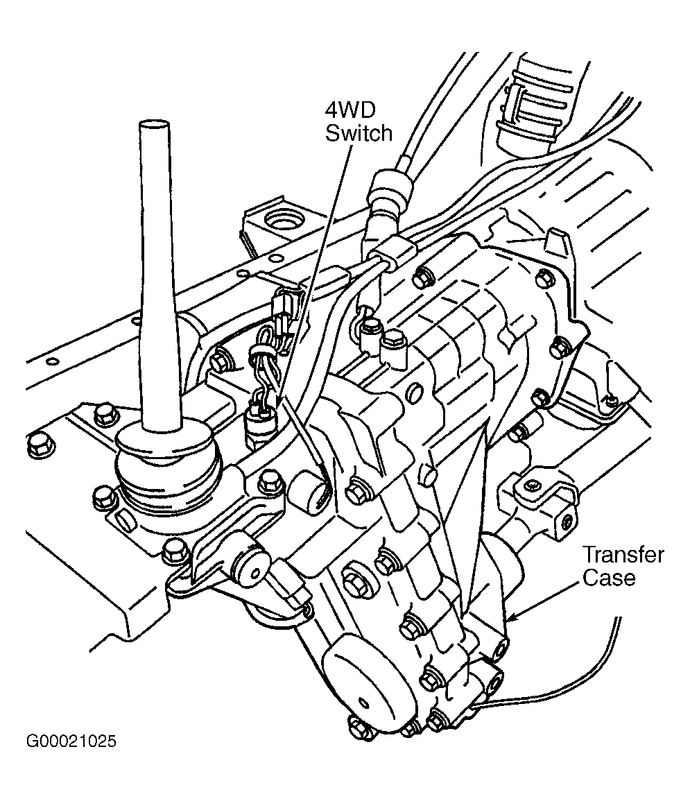 Courtesy of GENERAL MOTORS CORP.