Test D: Fuel Gauge Inoperative Or Inaccurate
- Turn ignition switch to RUN position. Check operation of fuel gauge. If fuel gauge is inoperative, go to next step. If fuel gauge is operating correctly, check for intermittent condition. See appropriate BODY CONTROL MODULES article.
- Turn ignition switch to LOCK position. Disconnect Powertrain Control Module (PCM) 35-pin harness connector C1. PCM is located under right side of instrument panel, below blower motor. Remove instrument cluster. See INSTRUMENT CLUSTER
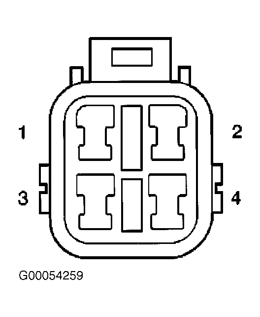
under REMOVAL & INSTALLATION. Disconnect fuel sending unit harness connector. Using Pin-Out Box (J-33431-C), connect Red lead to fuel sending unit harness connector terminal No. 2 (Blue/White wire) and other lead to ground. See Fig 1
. See FUEL GAUGE POSITION
table. If fuel gauge operates as specified, go to next step. If fuel gauge does not operate as specified, go to step 5
.
FUEL GAUGE POSITION
| Fuel Gauge Position |
Ohms |
| Full Tank |
10 Or Less |
| Half Tank |
30-35 |
| Empty Tank |
100 Or More |
 Courtesy of GENERAL MOTORS CORP.
- Measure resistance in Black wire between ground and fuel sending unit harness connector terminal No. 3. See Fig 1
. If resistance is 2 ohms or more, go to next step. If resistance is less than 2 ohms, go to step 6
.
- Repair open in Black wire between fuel sending unit and ground. Ground is located inside rear door near license plate lamps.
- Replace fuel sending unit and retest system.
- Measure resistance in Blue/White wire between fuel sending unit harness connector terminal No. 2 and instrument cluster harness connector C3 terminal No. 3. See Figure
and Fig 1
. If resistance is 2 ohms or more, go to next step. If resistance is less than 2 ohms, go to step 8
.
- Repair open in Yellow/Red wire between instrument cluster and fuel sending unit and retest system.
- Inspect for damage or loose connections in instrument cluster printed circuit. If printed circuit is damaged, go to next step. If printed circuit is not damaged, go to step 10
.
- Replace instrument cluster printed circuit and retest system.
- Replace fuel gauge and retest system. If concern still exist, diagnose PCM concern. See appropriate SELF-DIAGNOSTICS article in ENGINE PERFORMANCE.