Test V: Door Ajar Indicator Inoperative
- If power door systems diagnostic system check has been performed, go to next step. If power door systems diagnostic system check has been performed, go to POWER DOOR SYSTEMS DIAGNOSTIC SYSTEM CHECK under SELF-DIAGNOSTIC SYSTEM in BODY CONTROL MODULES - CORVETTE article. After performing power door systems diagnostic system check, go to next step.
- Verify operation of door ajar indicator by opening each door separately while engine is running. If door ajar message is present, problem may be intermittent. To diagnose intermittent, go to INTERMITTENT TROUBLE CODE DETERMINATION in BODY CONTROL MODULES - CORVETTE article. If door ajar message is not present, go to next step.
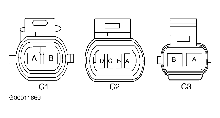
- Turn ignition off. Disconnect suspect door latch 4-pin connector C2. For driver's door, connect a fused jumper wire between suspect door latch connector C2 terminal "B" (Gray/Black wire) and ground. See Fig 1
. For passenger's door, connect a fused jumper wire between suspect door latch connector C2 terminal "C" (Black/White wire) and ground. On all applications, turn ignition on. If door ajar indicator illuminates, go to next step. If door ajar indicator does not illuminate, go to step 5
.
- Turn ignition off. For driver's door, connect a fused jumper wire between suspect door latch connector C2 terminals "B" (Gray/Black wire) and "D" (Black wire). For passenger's door, connect a fused jumper wire between suspect door latch connector C2 terminals "A" (Black wire) and "C" (Black/White wire). On all applications, turn ignition on. If door ajar indicator illuminates, go to step 8
. If door ajar indicator does not illuminate, go to step 10
.
- Check for open in Gray/Black or Black/White wire between suspect door latch, suspect Door Control Module (DCM) and Body Control Module (BCM). See WIRING DIAGRAMS in ANTI-THEFT SYSTEMS - CORVETTE article. Repair as necessary. After repairs, go to step 14
. If circuit is okay, go to next step.
- Reconnect door latch connector C2. Connect scan tool to Data Link Connector (DLC). Turn ignition on. Select BODY CONTROL MODULE INPUT DATA 2 data list and monitor suspect door ajar switch. Open suspect door. If scan tool indicates CLOSED, go to step 8
. If scan tool does not indicate CLOSED, go to step 9
.
- Check for poor connections at suspect door latch. Repair as necessary. After repairs, go to step 14
. If circuit is okay, go to step 11
.
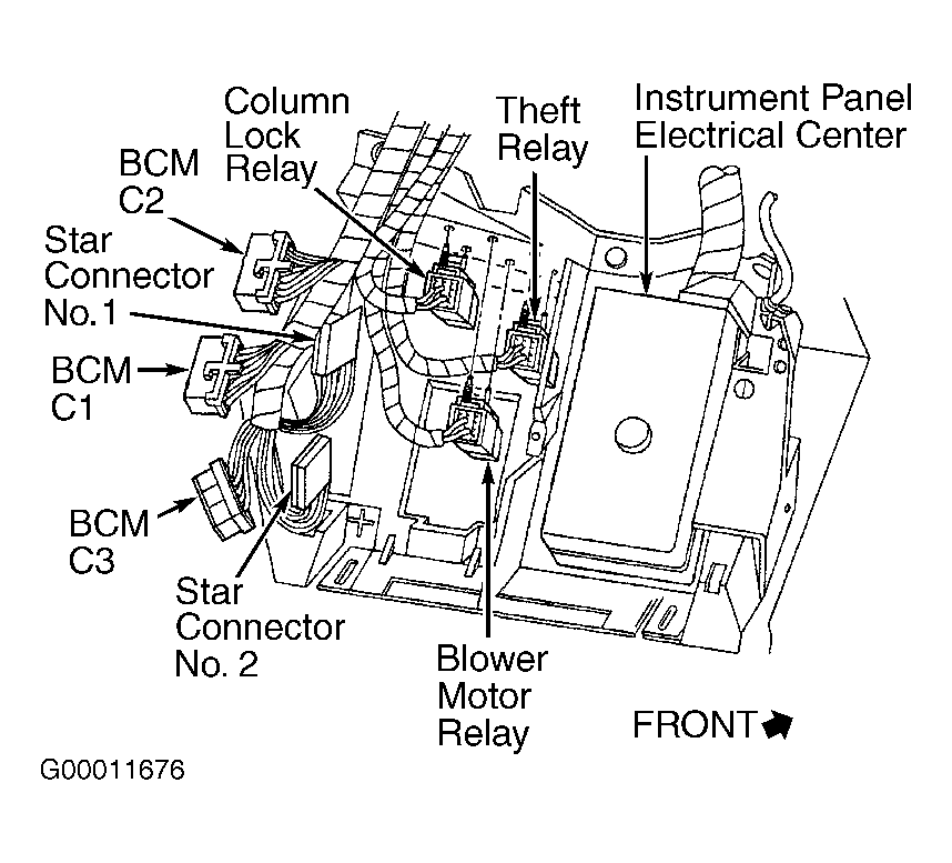
- Check for poor connections at BCM connectors. BCM is located under passenger's toe board. See Fig 2
. Repair as necessary. After repairs, go to step 14
. If circuit is okay, go to step 12
.
- Check for poor connections at IPC connectors. Repair as necessary. After repairs, go to step 14
. If circuit is okay, go to step 13
.
- Repair open in Black wire between suspect door latch and ground. See WIRING DIAGRAMS in ANTI-THEFT SYSTEMS - CORVETTE article. After repairs, go to step 14
.
- Replace suspect door latch. See DOOR LATCH under REMOVAL & INSTALLATION in POWER DOOR LOCKS - CORVETTE article. After repairs, go to step 14
.
- Replace BCM. See BODY CONTROL MODULE under REMOVAL & INSTALLATION in BODY CONTROL MODULES - CORVETTE article. After repairs, go to step 14
.
- Replace IPC. See INSTRUMENT PANEL CLUSTER
under REMOVAL & INSTALLATION. After repairs, go to next step.
- Recheck system operation to verify the repair. If system operates properly, repair is complete. If system does not operate properly, go to step 2
.
 Courtesy of GENERAL MOTORS CORP.
 Courtesy of GENERAL MOTORS CORP.