Test A: Chime Always On
- If audible warning diagnostic system check was performed, go to next step. If audible warning diagnostic system check was not performed, go to AUDIBLE WARNINGS DIAGNOSTIC SYSTEM CHECK
under SELF-DIAGNOSTIC SYSTEM. After performing audible warning diagnostic system check, go to next step.
- Turn ignition on. If any indicators/messages are present on IPC, diagnose those indicators/messages first. See SYMPTOM INDEX
table. If no indicators/messages are present on IPC, go to next step.
- Turn ignition off. Ensure headlight switch is off. Remove key from ignition. Open driver's door. If chime sounds, go to next step. If chime does not sound, problem is intermittent, go to INTERMITTENT TROUBLE CODE DETERMINATION in BODY CONTROL MODULES - CORVETTE article.
- Close driver's door. Connect scan tool to Data Link Connector (DLC). Turn ignition on. Using scan tool, select BODY CONTROL MODULE INPUT data list and monitor KEY IN IGNITION. If key in ignition status is INACTIVE, go to next step. If key in ignition status is ACTIVE, go to step 6
.
- Check for open in Black wire between ignition switch connector C2 terminal "E" and ground connection located at base of right "A" pillar. Repair as necessary. After repairs, go to step 11
. If circuit is okay, go to step 8
.
- Remove key from ignition. Disconnect BCM connectors. BCM is located under passenger's toe board. See Fig 1
. Check for short to ground between ground and BCM connector C2 terminal C14 (Light Green/Black wire). See Fig 2
. If short to ground is found, go to next step. If circuit is okay, go to step 9
.
- Disconnect ignition switch connector C1. Check for short to ground between ground and BCM connector C2 terminal C14 (Light Green/Black wire). Repair as necessary. After repairs, go to step 11
. If circuit is okay, go to step 10
.
- Check for open in Tan wire between ignition switch connector C2 terminal "D" and BCM connector C2 terminal C6. See Fig 2
. Repair as necessary. After repairs, go to step 11
. If circuit is okay, go to step 10
.
- Replace BCM. See REMOVAL & INSTALLATION in BODY CONTROL MODULES - CORVETTE article. After repairs, go to step 11
.
- Replace ignition switch. See IGNITION SWITCH
under REMOVAL & INSTALLATION. After repairs, go to next step.
- Recheck system operation to verify the repair. If system operates properly, repair is complete. If system does not operate properly, go to step 2
.
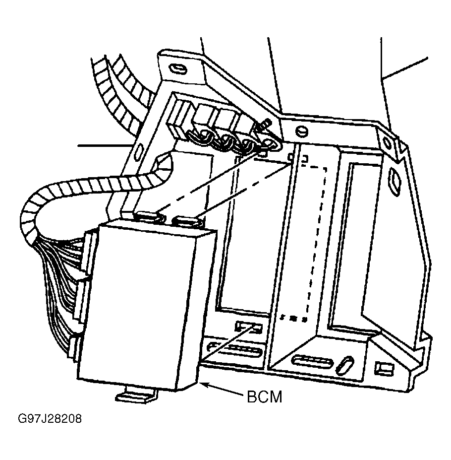 Courtesy of GENERAL MOTORS CORP.