Test B: Horn Inoperative In Content Theft Deterrent Alarm Mode
- If vehicle theft deterrent diagnostic system test has been performed, go to next step. If vehicle theft deterrent diagnostic system test has not been performed, go to VEHICLE THEFT DETERRENT DIAGNOSTIC SYSTEM TEST
under SELF-DIAGNOSTICS.
- Connect scan tool to Data Link Connector (DLC). DLC is located at lower left side of instrument panel, near steering column. Turn ignition switch to RUN position. Using scan tool, command horn relay on. If horn does not sound, go to next step. If horn sounds, perform this procedure while wiggling related wiring and connectors. This can often cause malfunction to appear.
- Press horn switch on steering wheel. If horn sounds, go to next step. If horn does not sound, repair horn circuit. See STEERING COLUMN SWITCHES
article. For 2002, see STEERING COLUMN SWITCHES
article.
- Disconnect Body Control Module (BCM) 24-pin Brown harness connector C3. BCM is located behind left side of instrument panel. Connect a 3-amp fused jumper wire between ground and BCM harness C3 connector terminal B7 (Black wire). See Fig 1
. If horn does not sound, go to next step. If horn sounds, go to step 6
.
- Check for open or short to voltage in Black wire between horn switch and horn relay. Horn relay is located under right side of instrument panel, below convenience center.
- Check for poor connections and loose or corroded terminals at BCM harness connector C3. If problem is not found, go to next step. If problem is found, repair as necessary. After repairs, go to step 8
.
- Replace and program BCM. See BODY CONTROL MODULE
under REMOVAL & INSTALLATION. See BODY CONTROL MODULE PROGRAMMING/REGULAR PRODUCTION OPTION CONFIGURATION
under PROGRAMMING. After repairs, go to next step.
- Operate system in order to verify repair. If condition has been corrected, system is okay. If condition has not been corrected, go to step 3
.
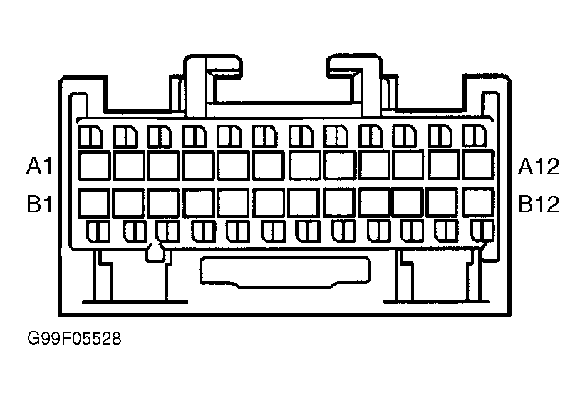 Courtesy of GENERAL MOTORS CORP.