Wheel Drive Shaft Inner Joint and Boot Replacement
FRONT DRIVE AXLE- DRIVE SHAFT INNER JOINT AND BOOTDisassembly Procedure
^ Tools Required
- J 8059 Snap Ring Pliers
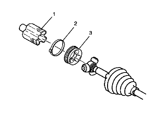
1. Disconnect the swage ring from the halfshaft bar using a hand grinder to cut through the ring taking care not to damage the halfshaft bar.
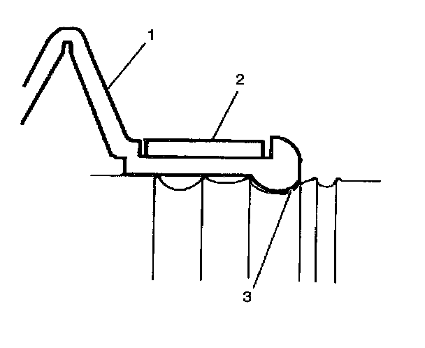
Important: Do not cut through the halfshaft inboard boot and damage sealing surface of the outer housing (1) and the trilobal tripot bushing (3).
2. Remove the larger boot retaining clamp (2) from the tripot joint with side cutter and dispose.
3. Separate the halfshaft inboard boot from the trilobal tripot bushing (3) at the large diameter.
4. Slide the boot away from the joint along the halfshaft bar.
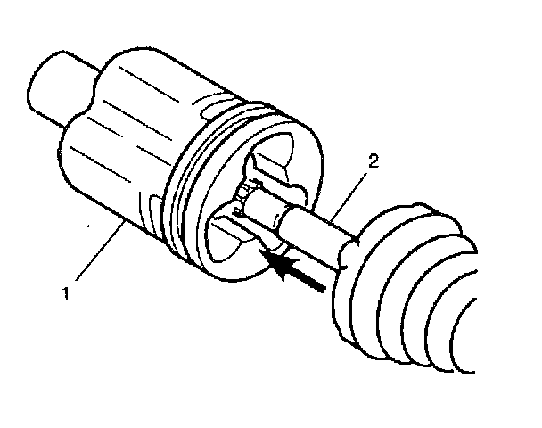
5. Remove the housing (1) from the tripot joint spider and the halfshaft bar (2).
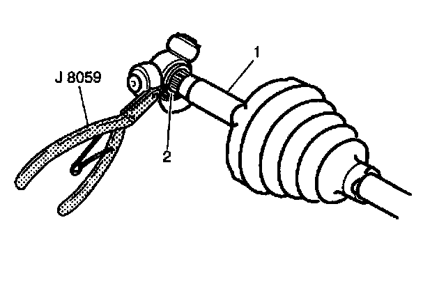
6. Spread spacer ring (2) using J 8059.
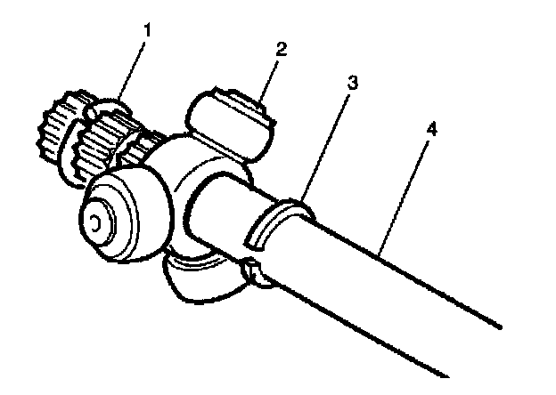
7. Slide the spacer ring (3) and tripot joint spider (2) back on halfshaft bar (4).
8. Remove the halfshaft bar retaining ring (1) from the groove on the halfshaft bar (4).
9. Slide tripot joint spider assembly (2) off of the halfshaft bar (4).
10. Clean the tripot joint spider assembly (2) and the housing thoroughly with cleaning solvent.
11. Remove all traces of old grease and any contaminates.
12. Dry all the parts.
13. Remove the trilobal tripot bushing from the housing.
14. Remove the spacer ring (3) and the boot from the halfshaft bar (4).
15. Inspect the following parts for damage or wear:
^ The halfshaft inboard boot
^ The tripot joint spider assembly (2)
^ The housing
^ The trilobal tripot bushing
Assembly Procedure
^ Tools Required
- J 35910 Drive Axle Seal Clamp Pliers
- J 41048 Drive Axle Swage Ring Clamp
- J 36652 Drive Axle Clamp Swage Tool
1. Place the new small boot clamp (2) onto the small end of the joint boot (1). Slide the joint boot (1) and the small boot clamp (2) onto the halfshaft bar.
2. Position the small end of the joint boot (1) into the joint boot groove (3) on the halfshaft bar.
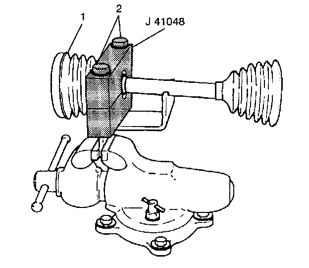
3. Mount J41048 into a vise.
4. Position the inboard end (1) of the halfshaft assembly on the lower half of J41048.
5. Align the top of the boot neck on the bottom die using the indicator.
6. Place the top half of the J 41048 on the lower half of the J41048.
7. Before proceeding, ensure that there are no pinch points on the halfshaft inboard boot. This could cause damage to the halfshaft inboard boot.
8. Insert the bolts (2).
9. Tighten the bolts by hand until snug.
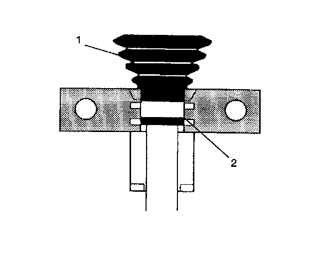
10. Align the following items:
^ The halfshaft inboard boot (1)
^ The housing
^ The swage ring (2)
^ Tighten
Each bolt of J41048 180 degrees at a time using a ratchet wrench. Alternate between each bolt until both sides are bosomed.
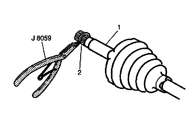
11. Install the spacer ring (2) on the halfshaft bar (1) and beyond the second groove using J 8059.
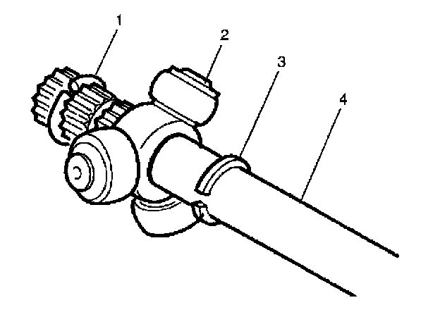
Important: Ensure that the counterbored face of the tripot joint spider (2) faces toward the end of the halfshaft bar (4).
12. Slide the tripot joint spider assembly (2) toward the spacer ring (1) as far as it will go on the halfshaft bar (4).
13. Install the halfshaft bar retaining ring (1) in the groove of the halfshaft bar.
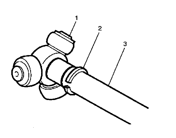
14. Slide the tripot joint spider assembly (1) back towards the end of the halfshaft bar (3).
15. Reseat the spacer ring (2) in the groove on the halfshaft bar (3).
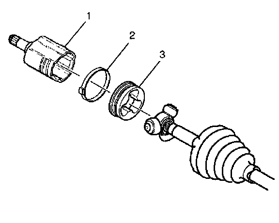
Important: Ensure the trilobal tripot bushing (3) is flush with the face of the housing (1).
16. Place approximately half of the grease from the service kit in the halfshaft inboard boot. Use the remainder of the grease to repack the housing.
17. Install the trilobal tripot bushing (3) to the housing (1).
18. Position the larger new boot retaining clamp (2) on the halfshaft inboard boot.
19. Slide the housing (1) over the tripot joint spider assembly on the halfshaft bar.
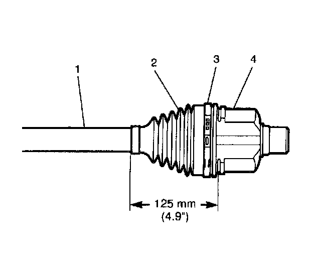
20. Slide the large diameter of the halfshaft inboard boot (2), with the larger clamp (3) in place, over the outside of the trilobal tripot bushing and locate the lip of the boot in the groove.
Important: The halfshaft inboard boot (2) must not be dimpled, stretched out or out of shape in any way. If the halfshaft inboard boot (2) is not shaped correctly, carefully insert a thin, flat, blunt tool (no sharp edges) between the large boot opening and the trilobal tripot bushing in order to equalize the pressure. Shape the halfshaft inboard boot (2) properly by hand. Remove the thin, flat, blunt tool.
21. Position the joint assembly at the proper vehicle dimension.
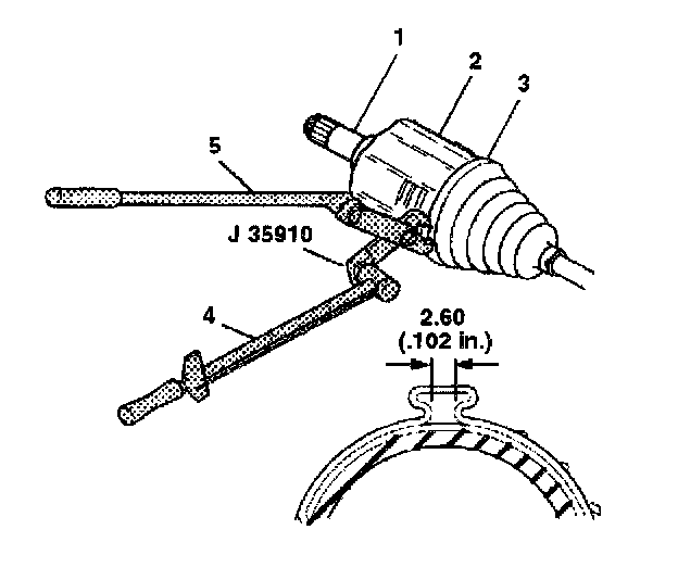
22. Align the following items while latching:
^ The halfshaft inboard boot
^ The tripot housing (2)
^ The large boot retaining clamp (3)
^ Tighten
Crimp the boot retaining clamp (3) with J 35910 to 176 Nm (130 ft. lbs.). Add the breaker bar (5) and the torque wrench (4) to J 35910 if necessary.