Vacuum Brake Booster Replacement
Removal Procedure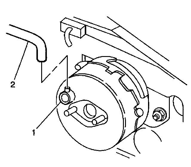
1. Remove the air cleaner and the duct. Refer to Air Filter Element Replacement.
2. Remove the vacuum hose (2) from the vacuum check valve (1). Reposition the vacuum hose.
3. Remove the throttle cables from the throttle body and the bracket. Refer to Accelerator Controls Cable Replacement.
4. Remove the heater inlet pipe. Refer to Heater Pipe Replacement - Inlet in Heating and Air Conditioning
5. Remove the fuel lines from the pipes and the vapor line. Refer to Fuel Hose/Pipes Replacement (Engine Compartment) (Engine pipes).
6. Remove the ABS hydraulic modulator/master cylinder. Refer to Master Cylinder Replacement.
7. Remove the EGR tube.
8. Remove exhaust crossover. Refer to Exhaust Crossover Pipe Replacement.
9. Remove the transmission fluid filler tube. Refer to Fluid Filler Tube Replacement.
10. Remove the left side instrument panel insulator. Refer to Closeout/Insulator Panel Replacement -Left in Instrument Panel, Gauges and Warning Indicators.
11. Remove the knee bolster. Refer to Knee Bolster Replacement in Instrument Panel, Gauges and Warning Indicators.
12. Disable the SIR system. Refer to Disabling the SIR System in Restraint Systems.
Notice: When disconnecting the pushrod from the brake pedal, the brake pedal must be held stationary or damage to the brake switch may result.
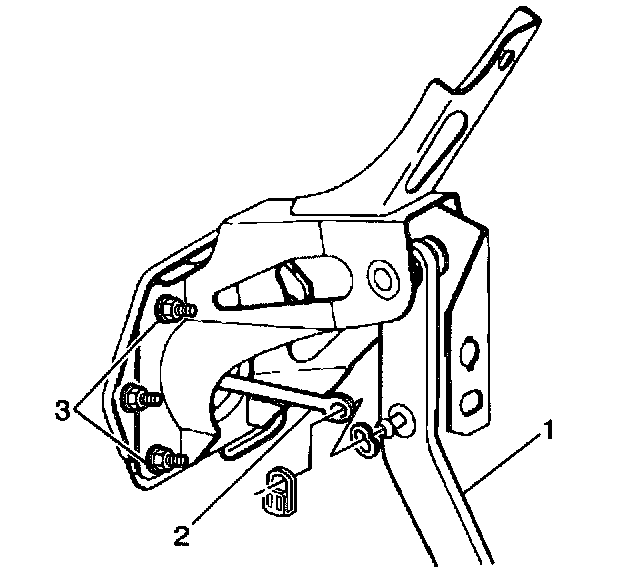
13. Remove the brake booster push rod (2) from the brake pedal (1).
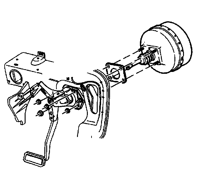
14. Remove the brake booster mounting nuts.
15. Remove the brake booster.
Installation Procedure
Caution: When replacing the power booster brake, make sure that the cruise control cable is not routed between the booster and the cowl. If the cable is damaged or pinched, it must be replaced. Failure to do this could result in personal injury.
Notice: Proper stoplamp switch adjustment is essential. Improper stoplamp switch adjustment may cause brake drag, heat buildup and excessive brake lining wear.
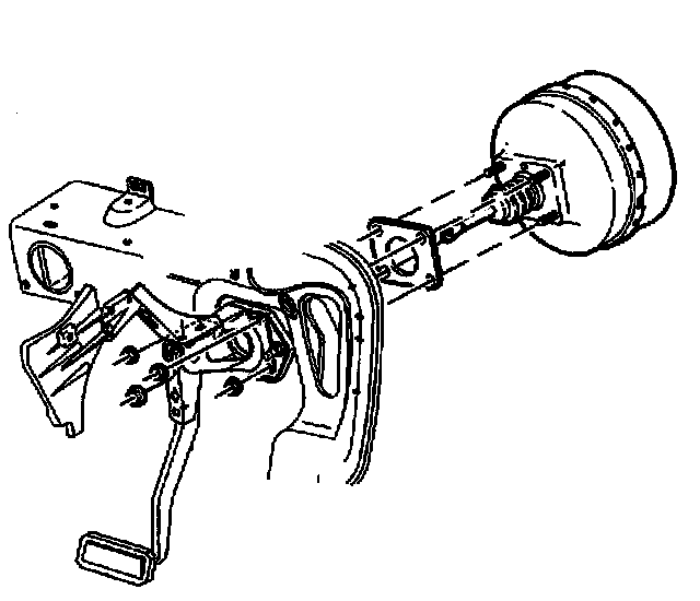
1. Position the brake booster to the cowl and the mounting plate.
Notice: Refer to Fastener Notice in Service Precautions.
2. Install the brake booster mounting nuts.
^ Tighten the brake booster mounting nuts to 25 Nm (18 ft. lbs.).
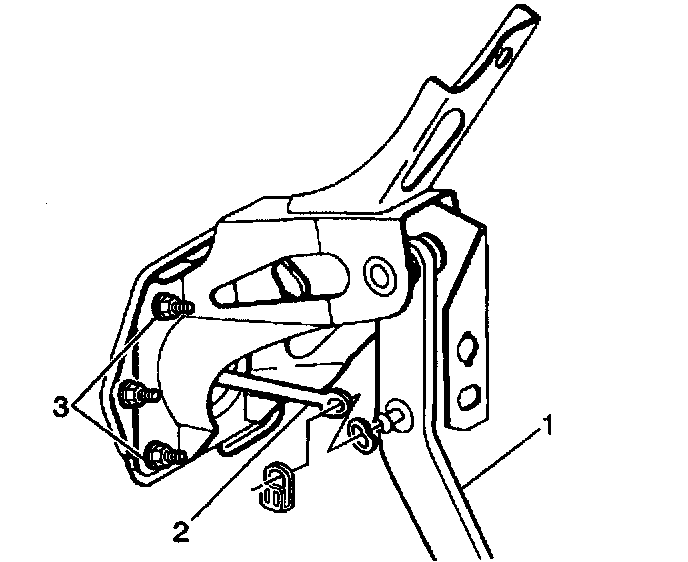
3. Install the brake booster push rod (2) to the brake pedal (1).
4. Adjust the stoplamp switch. Refer to Stoplamp Switch Adjustment.
5. Enable the SIR system. Refer to Enabling the SIR System in Restraint Systems.
6. Install the knee bolster. Refer to Knee Bolster Replacement in Instrument Panel, Gauges and Warning Indicators.
7. Install the left side instrument panel insulator. Refer to Closeout/Insulator Panel Replacement - Left in Instrument Panel, Gauges and Warning Indicators.
8. Install the transmission fluid filler tube. Refer to Fluid Filler Tube Replacement.
9. Install exhaust crossover. Refer to Exhaust Crossover Pipe Replacement.
10. Install the EGR tube.
11. Install the ABS hydraulic modulator/master cylinder. Refer to Master Cylinder Replacement.
12. Install the fuel lines to the pipes and the vapor line. Refer to Fuel Hose/Pipes Replacement (Engine Compartment) (Engine pipes) or Fuel Hose/Pipes Replacement (Engine Compartment) (Engine Compartment).
13. Install the heater inlet pipe. Refer to Heater Pipe Replacement - Inlet in Heating and Air Conditioning.
14. Install the throttle cables to the throttle body and the bracket. Refer to Accelerator Controls Cable Replacement.
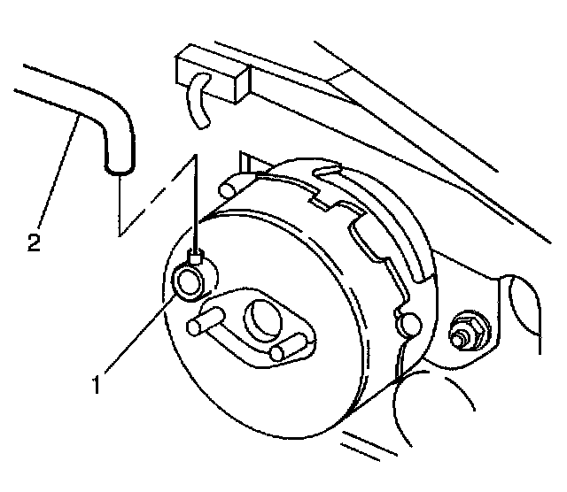
15. Install the vacuum hose (2) to the check valve (1).
16. Install the air cleaner and duct assembly. Refer to Air Filter Element Replacement.