Hydraulic Control Assembly - Antilock Brakes: Service and Repair
Removal Procedure
Caution: For safety reasons, the Brake Pressure Modulator Valve (BPMV) must not be repaired, the complete unit must be replaced. With the exception of the EBCM/EBTCM, no screws may be loosened. If screws are loosened, it will not be possible to get the brake circuits leak-tight and personal injury may result.
1. Turn the ignition switch to the OFF position.
2. Remove the attaching bolts for the cruise control module.
3. Swing the cruise control module off to the side.
4. Remove the air cleaner housing from the engine compartment. Refer to Air Cleaner Assembly Replacement.
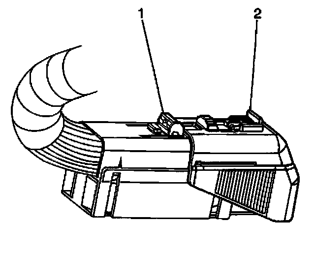
5. Disengage the red locking tab from the connector (1).
6. Push down lock tab (1) and then move sliding connector cover (2) to the open position.
7. Disconnect the EBCM harness connector.
Important: Note the locations of the brake pipes in order to aid in installation.
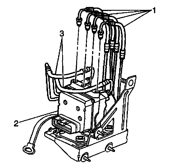
8. Disconnect the four wheel brake pipes (1) from the BPMV (2).
9. Swing the four wheel brake pipes out of the way only after covering the open pipes to avoid dripping or being contaminated.
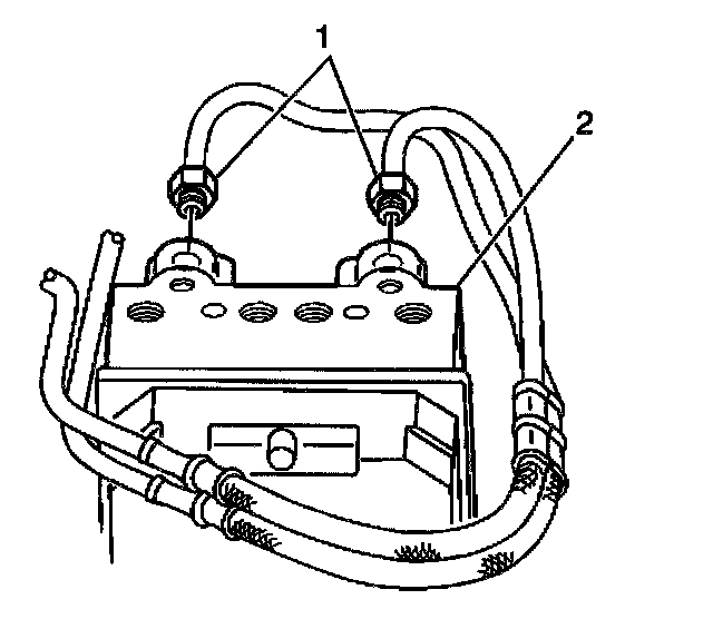
10. Disconnect the master cylinder brake pipes (1) from the BPMV (2).
11. Loosen the brake pipes but do not remove the brake pipes from the master cylinder.
12. Swing the two master cylinder brake pipes out of the way only after covering the open pipes to avoid dripping or being contaminated.
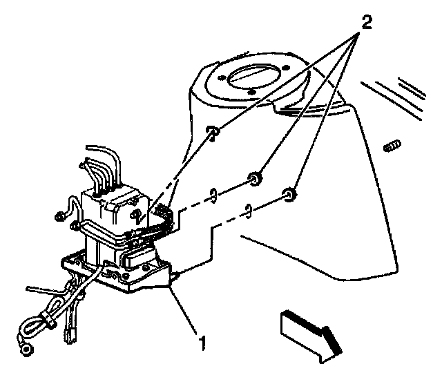
13. Remove the three BPMV mounting bracket nuts (2) from the inner wheel housing mount surface of the strut tower.
14. Reinstall the top nut upside down on the top stud.
15. Lightly tap on the bottom of the nut until the stud has loosened up.
16. Disconnect the ground strap between the EBCM assembly and the chassis.
17. Remove the BPMV mounting bracket and EBCM assembly from the vehicle.
Notice: When removing the brake pressure modulator valve, protect the vehicle exterior from possible brake fluid spillage. Brake fluid can cause damage to painted surfaces.
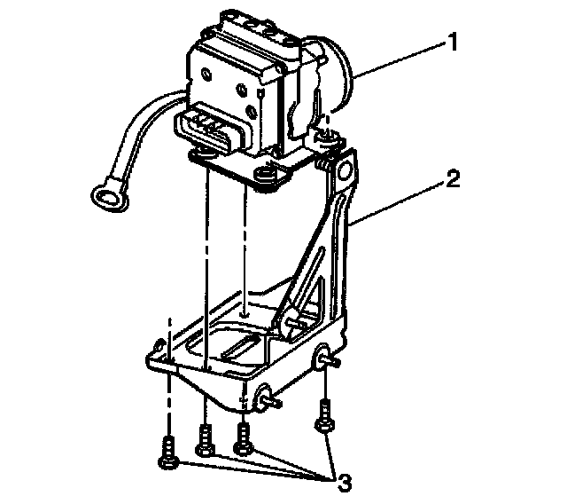
18. Remove the four bolts (3) that connect the BPMV (1) to the mounting bracket (2).
19. Remove EBCM if replacing the BPMV only. Refer to Electronic Brake Control Module (EBCM) Replacement.
Installation Procedure
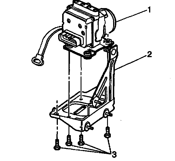
1. Install EBCM onto the BPMV (1) if replacing the BPMV only. Refer to Electronic Brake Control Module (EBCM) Replacement.
2. Install BPMV and EBCM as an assembly to the mounting bracket.
3. Install the four bolts (3) that connects the BPMV assembly (1) to the mounting bracket (2).
^ Tighten the four bolts (3) that connect the BPMV (1) to the mounting bracket (2) to 10 Nm (84 inch lbs.).
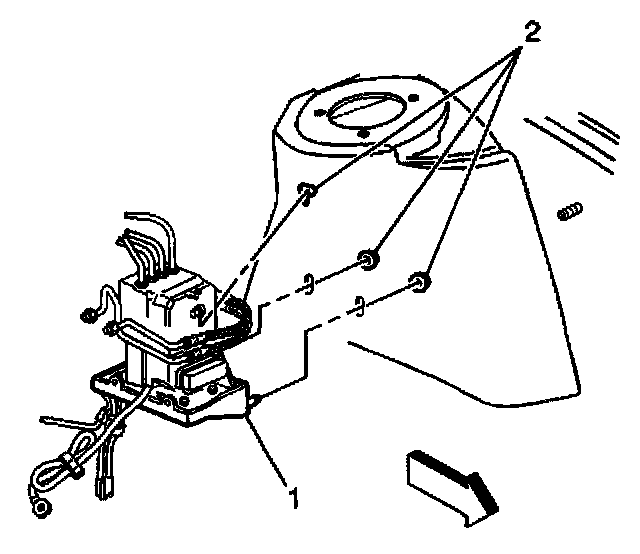
4. Install the BPMV bracket to the strut tower.
5. Install the three nuts (2) that attach the BPMV mounting bracket to the strut tower.
Notice: Refer to Fastener Notice in Service Precautions.
^ Tighten the three BPMV mounting bracket nuts to 10 Nm (84 inch lbs.).
^ Reposition any lines or hoses that were moved out of place.
Important: If a new BPMV is being installed, remove the shipping plugs from the valve openings during the next few steps when ready.
Caution: Make sure brake pipes are correctly connected to brake pressure modulator valve. If brake pipes are switched by mistake, wheel lockup will occur and personal injury may result. The only two ways this condition can be detected are by using a Scan Tool or by doing an Antilock stop.
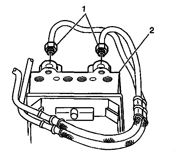
6. Install the master cylinder brake pipes (1) into the BPMV (2).
^ Tighten the master cylinder brake pipe fittings to 24 Nm (18 ft. lbs.).
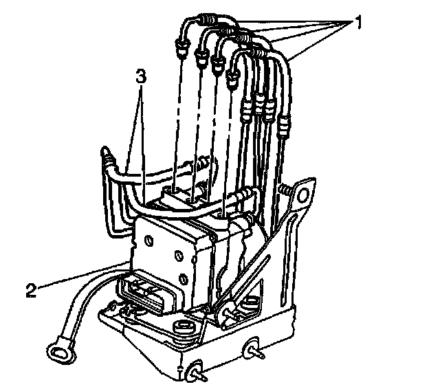
7. Install the four wheel brake pipes (1) on the BPMV (2).
^ Tighten all four wheel brake pipe fittings to 24 Nm (18 ft. lbs.).
8. Reconnect the ground strap between the EBCM assembly and the chassis.
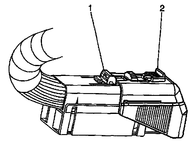
9. Connect the EBCM harness connector.
10. Push down lock tab (1) and then move sliding connector cover (2) back in home position to lock.
11. Insert red locking tab back in place.
12. Reinstall the air cleaner housing. Refer to Air Cleaner Assembly Replacement.
13. Reinstall the cruise control module.
14. When all procedures have been completed, the automated ABS bleed procedure is required. Refer to Automated Bleed Procedure.