Video Screen Backlighting Inoperative
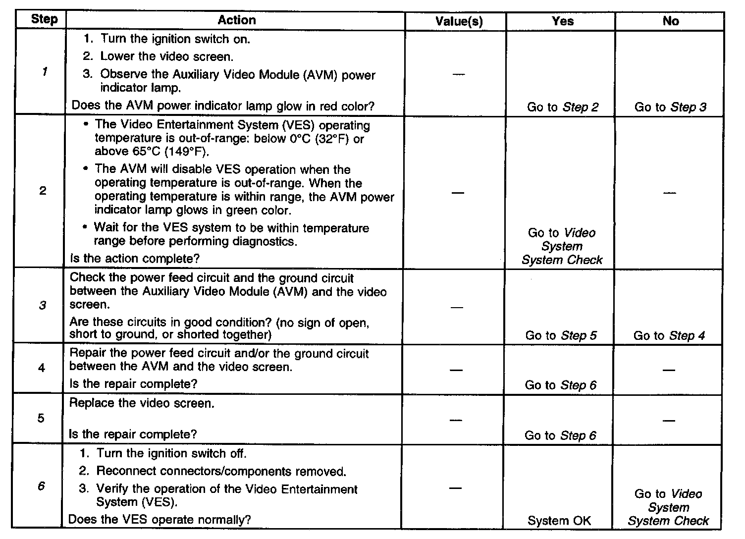
Diagnostic Chart:
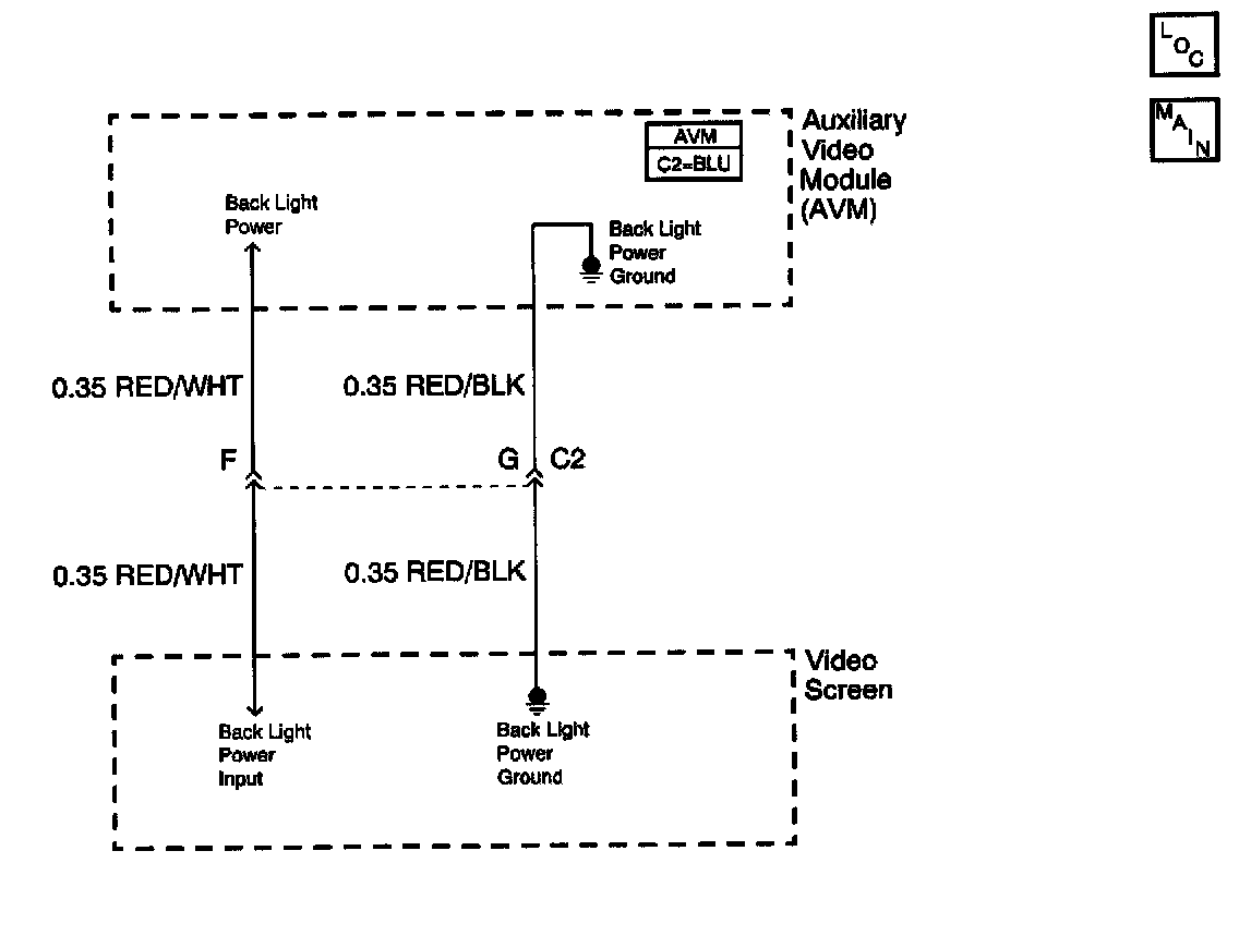
Schematic:
CIRCUIT DESCRIPTION
The Liquid Crystal Display (LCD) video screen turns on its backlighting when the ignition switch is on and the video screen is in the down position. The Auxiliary Video Module (AVM) controls which source of video signal gets routed to the video display screen. When the AVM switch is set to VCP, the AVM routes the Video Cassette Player (VCP) video signal to the video screen. When the AVM switch is set to the AUX position, the video signal that is connected to the auxiliary RCA input jacks gets routed to the display screen. The AVM contains a temperature sensor that controls system operation during temperature extremes. When the AVM detects that the operating temperature is out-of-range, below 0°C (32°F) or above 65°C (149°F), the AVM power indicator lamp glows in red color, and also turns off the video display. The AVM power indicator lamp glows in green color when the VES operating temperature is within range.
DIAGNOSTIC AIDS
^ Check for the following conditions:
- An open in the ground circuit between the AVM and the video screen.
- An open in the power teed circuit between the AVM and the video screen.
^ An intermittent failure may be very difficult to detect and to diagnose accurately. Faulty electrical connections or wiring causes most intermittent problems. When an intermittent condition is suspected, check the suspected circuits for the following conditions:
- Poor mating of connector halves or backed out terminals.
- Improperly formed or damaged terminals.
- Wire chafing.
- Poor wire to terminal connections.
- Dirty or corroded terminals.
- Damage to connector bodies.
- Wire broken inside the insulation.
TEST DESCRIPTION
The number(s) below refer to the step number(s) on the diagnostic table.
1. Checks if the VES operating temperature is within range.
3. Checks the integrity of the video screen power and ground circuits.
6. Verifies repairs made to the VES.