Later Design
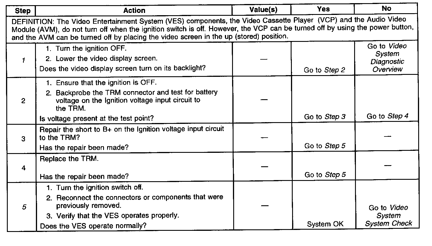
Diagnostic Chart:
Schematic:
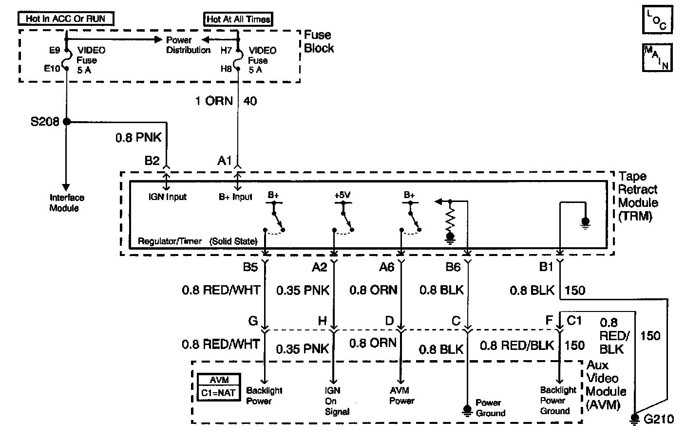
CIRCUIT DESCRIPTION
The Video Entertainment System (VES) contains the Auxiliary Video Module (AVM), the Interface Module (IM), and the Tape Retract Module (TRM). The TRM receives voltage at all times from the RR FOG LP fuse located in the fuse block. The TRM receives ignition voltage from the VIDEO ENT fuse when the ignition switch is on. When the key is on, the TRM in turn supplies battery voltage, the ignition signal, and the power ground signal to the AVM and battery voltage to the Video Cassette Player (VCP).
DIAGNOSTIC AIDS
^ Check for a Short to Battery voltage on the IGN voltage input to the TRM.
^ An intermittent failure may be very difficult to detect and to diagnose accurately. Faulty electrical connections or wiring causes most intermittent problems. When an intermittent condition is suspected, check the suspected circuits for the following conditions:
- Improperly formed or damaged terminals.
- Wire chafing.
- Damage to connector bodies.
TEST DESCRIPTION
The number(s) below refer to the step number(s) on the diagnostic table.
1. Determines whether the LCD screen turns the backlight on when the ignition is not on.
5. Verifies repairs made to the VES system.