Video Cassette Player (VCP) Inoperative
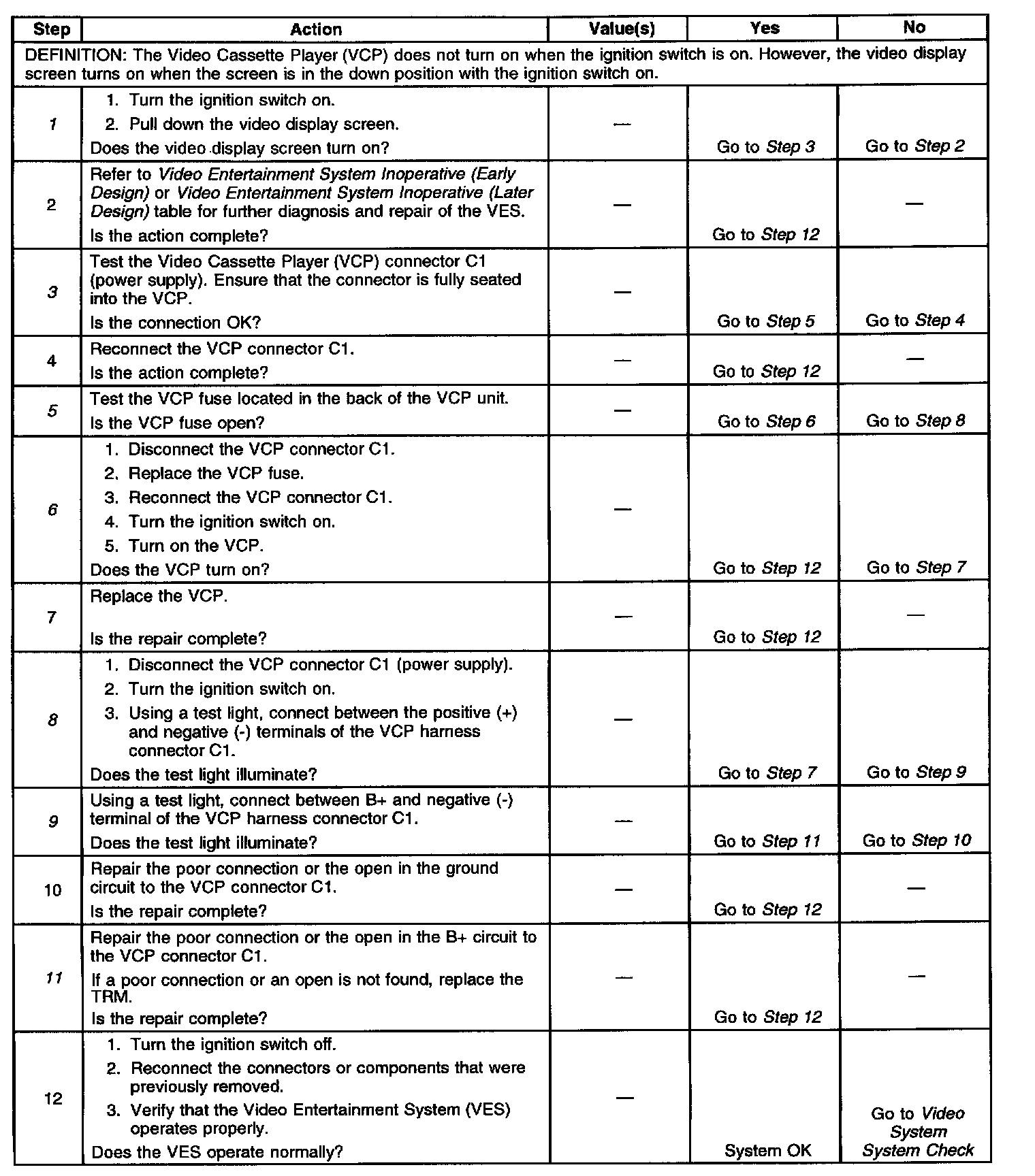
Diagnostic Chart:
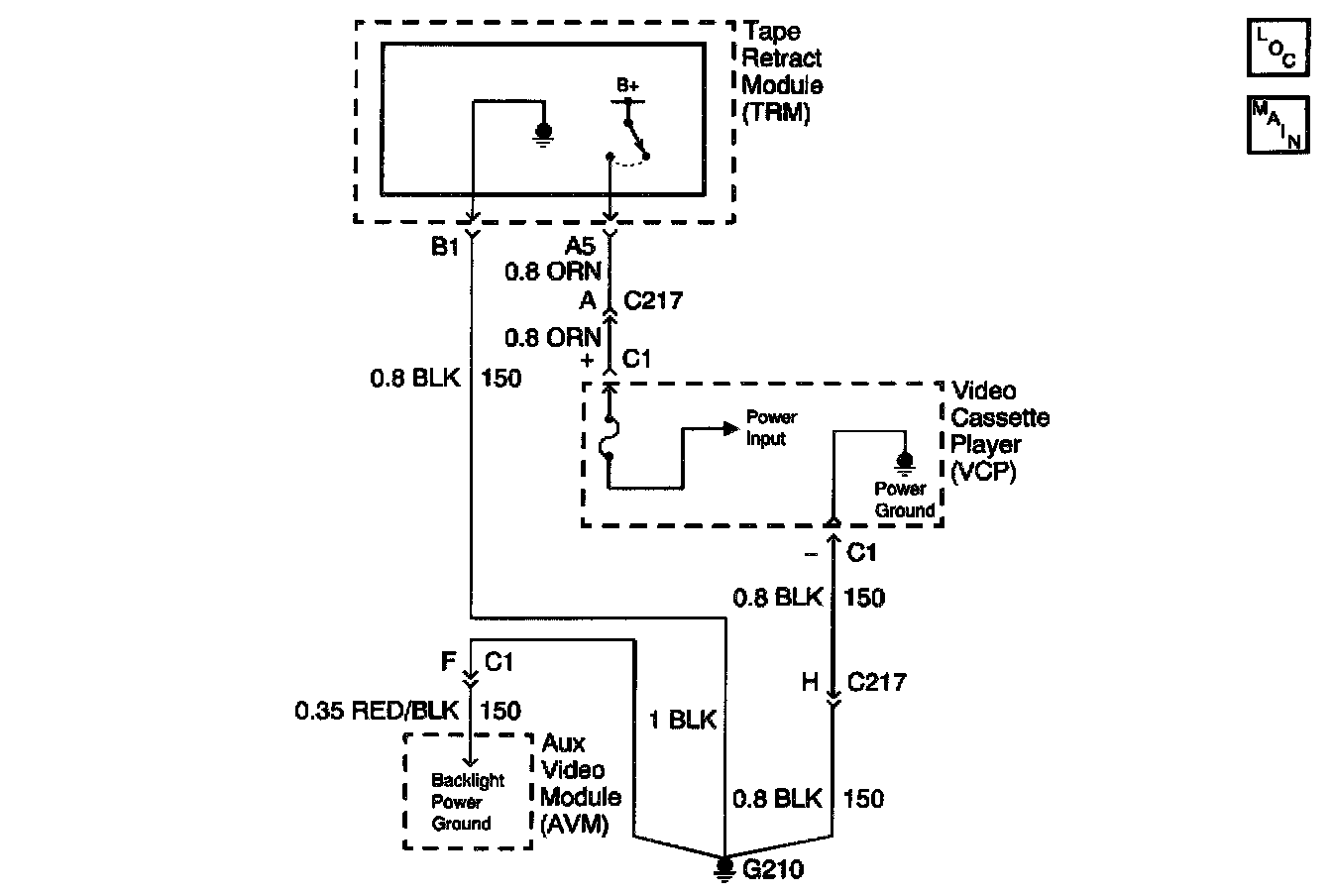
Schematic:
CIRCUIT DESCRIPTION
The Video Cassette Player (VCP) plays pre-recorded VHS cassettes. The Tape Retract Module (TRM) supplies the VCP with voltage when the ignition is on and the LCD display screen is pulled down in the viewing position. When the ignition is turned off, the TRM and the VCP lose power at the same time. The TRM has a timer function that allows battery voltage to be restored to the VCP for 12 seconds to retract the cassette tape from the playback head, thus preventing cassette damage. Note that the "cassette in" indicator lamp in the VCP turns on during the 12 second period when the VHS tape is unloaded in the VCP.
DIAGNOSTIC AIDS
^ Check for the following conditions:
- An open in the voltage supply from the TRM to the VCP.
- An open in the ground circuit between the TRM and the VCP.
- A faulty TRM.
- A faulty VCP.
^ An intermittent failure may be very difficult to detect and to diagnose accurately. Faulty electrical connections or wiring causes most intermittent problems. When an intermittent condition is suspected, check the suspected circuits for the following conditions:
- Poor mating of connector halves or backed out terminals.
- Improperly formed or damaged terminals.
- Wire chafing.
- Poor wire to terminal connections.
- Dirty or corroded terminals.
- Damage to connector bodies.
- Wire broken inside the insulation.
TEST DESCRIPTION
The number(s) below refer to the step number(s) on the diagnostic table.
1. Tests if the video display screen turns on correctly.
3. Tests if the VCP power supply connector is backed out.
5. Tests if the VCP fuse is open.
6. Tests if the VCP fuse is open due to an internal short in the VCP or overload condition.
8. Tests for power at the VCP power supply connector.
9. Tests for an open in the ground circuit to the VCP connector.
11. Tests for an open in the B+ circuit to the VCP connector.
12. Verifies repairs made to the VES.