Rear Suspension
Disassembly ProcedureTools Required
^ J 34013-B Strut Compressor
^ J 34013-20 Damper Rod Clamp
^ J 34013-197 Alignment Rod
^ J 34013-125 Upper Strut Adapter
^ J 34013-971 Lower Strut Adapter
^ J 42991 Strut Rod Nut Socket
1. Remove the strut from the vehicle. Refer to Strut Assembly Replacement.
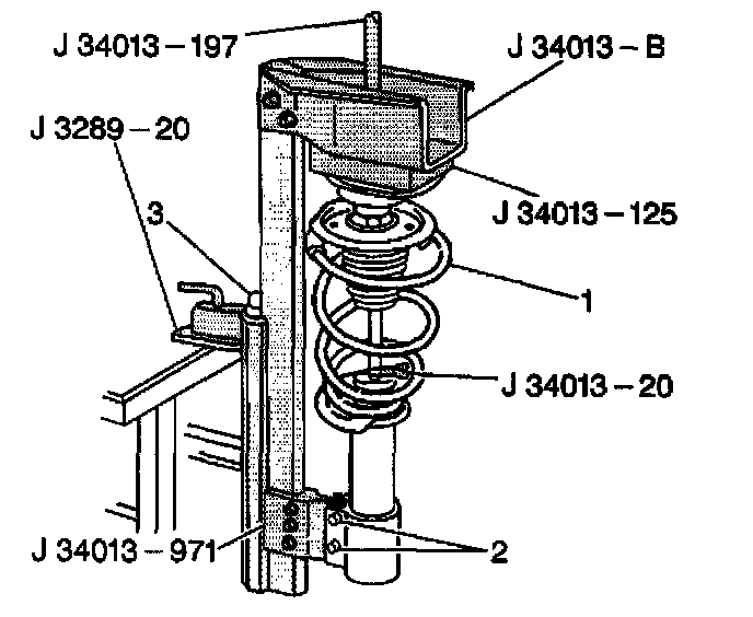
2. Install the strut to the J 34013-B. Use wing nuts to secure the tool to the mounting holes C (1) and E/K (3). Position the wide end of the adapter outboard.
Important: Align the J 34013-971 and the J 34013-125 so that the tools may open and close together. The tools will not open If the tools do not align properly.
3. Install the J 34013-971 and the J 34013-125.
4. Install the strut to the top of the J 34013-B.
5. Install the strut into the J 34013-971 and the J 34013-125.
6. Close the J 34013-971 and the J 34013-125.
7. Install the locking pins through the holes of J 34013-971 and the strut lower mounting holes.
8. Turn the screw (3) on the J 34013-B counterclockwise to raise the strut up to the J 34013- 125.
9. Compress the spring approximately 13 mm (0.50 inch) or three to four complete turns of the operating screw.
Caution: Do not over compress the spring. Severe overloading may cause tool failure which could result in bodily injury.
10. Insert the J 42991 on the nut.
11. Hold shaft with a T-45 Torx bit.
12. Use the J 42991 to remove the nut while preventing the rod from rotating with a T-45 Torx bit.
13. Discard the strut nut.
14. Turn the operating screw (3) on the J 34013-B clockwise to fully relieve the spring compression.
Assembly Procedure
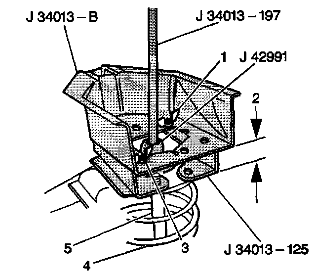
1. Install the strut to the J 34013-B. Use wing nuts to secure the tool to the mounting holes C and E/K. Position the wide end of the adapter outboard.
Important: Align the J 34013-971 and the J 34013-125 so that the tools may open and close together. The tools will not open if the tools are not aligned properly.
2. Install the J 34013-971 and the J 34013-125.
3. Install the strut to the J 34013-971 and the J 34013-125.
4. Close the J 34013-971 and the J 34013-125.
Important:
^ Use only one pin for mounting.
^ Position the top of the shock absorber flat against J 34013-125. The shock absorber will not align correctly if the shock absorber does not lay flat against the tool.
5. Install the locking pin through the lower hole of the J 34013-B and the lower knuckle mounting hole of the strut.
6. Install the strut to the top of the J 34013-B.
7. Install the spring to the strut. Ensure to position the upper and lower spring seats correctly.
8. Install the remaining components to the strut.
9. Fully extend the strut shaft.
10. Attach the J 34013-20. This prevents the shaft from retracting during compression.
Important: Align the J 34013-197 Alignment Rod straight with the strut. If the J 34013-197 Alignment Rod is not aligned, repeat steps 1 through 12 until the tool is straight.
11. Insert the J 34013-197 Alignment Rod down through the top of the J 34013-B and onto the shaft.
12. Slowly turn the operating screw counterclockwise in order to compress the spring until the threaded portion of the strut shaft is through the top of the strut.
Caution: Do not over compress the spring. Severe overloading may cause tool failure which could result in bodily injury.
Notice: Keep the strut rod in a stationary position when you tighten the strut nut. Turning the strut rod may damage the strut.
13. Insert a new strut nut on the strut rod.
Notice: Refer lo Fastener Notice in Service Precautions.
14. Place the J 42991 on the shock absorber nut.
Tighten the shock absorber rod to upper mount to 75 Nm (55 ft. lbs.).
15. Insert a T-45 torx through the J 34013-197 Alignment Rod.
16. Tighten the shock absorber nut while holding the shaft with a T-45 torx.
17. Remove the following tools from the J 34013-B:
17.1. Remove the J 34013-20.
17.2. Remove the J 34013-197Alignment Rod.
17.3. Remove the J 42991.
18. Remove the strut from the J 34013-B.
19. Install the strut to the vehicle. Refer to Strut Assembly Replacement.