Suspension - Front of Vehicle Too Low or Bottoms Out
File in Section: 03 - SuspensionBulletin No.: 02-03-08-002
Date: February, 2002
TECHNICAL
Subject:
Front of Vehicle Sits Too Low, Bottoms Out Over Bumps
(Replace Front Coil Springs, Inspect/Replace Frame and Mount)
Models:
2000-2001 Chevrolet Impala
with RPO 9C1 Police Car and 9C3 SEO Vehicle Police Car, Limited Content Built Prior to VIN Breakpoint 29140498
Condition
Some customers may comment that the front of the vehicle sits too low and bottoms out over bumps.
Cause
This condition may be caused by the additional weight of the Police Package added to the vehicle.
Correction
Follow the service procedure below. Measuring J and K Trim Heights
1. Place the vehicle on a level surface such as an alignment rack.
2. Set the tire pressures on all Police vehicles.
Tire Inflation Pressure Specifications
Set the tire inflation pressure for Police Vehicles at 240 kPa (35 psi).
3. Verify the fuel level. Add additional weight if necessary to simulate a full tank.
4. Remove any additional items from the vehicle's interior.
5. Empty the rear compartment except for the spare tire.
6. Close the deck lid.
7. Close the doors
8. Close the hood.
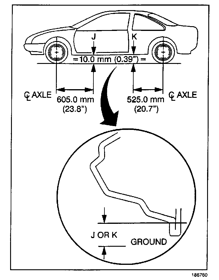
Important:
^ Lift the front bumper at the center 38 mm (1.05 in) and gently release allowing the vehicle to settle. Push the bumper down 38 mm (1.05 in) and gently release allowing the vehicle to rise. Repeat this procedure for the rear bumper.
^ All dimensions are measured vertical to the ground.
9. Measure the J and K heights 230 mm-250 mm (9.06 in-9.84 in).
If the J and K heights are below the specifications listed above, replace the front strut coil springs, P/N 22133025. Refer to Strut, Strut Component and/or Spring Replacement in the Service Manual (SI2000 Document ID # 652878).
Frame Inspection/Replacement
1. Raise the vehicle.
Important:
^ Vehicles with damage to the front frame rail due to impacts with an object are not covered under warranty.
^ Scrapes on the front frame rail will be covered under warranty.
2. Inspect the frame along the front edge for damage due to the vehicle bottoming out.
3. Inspect the frame for bending using a straight edge along the right side of the frame rail below the engine mount.
4. Remove the frame if the frame is damaged or bent. Refer to Frame Replacement in Body and Accessories in the Service Manual (SI2000 Document ID # 728902).
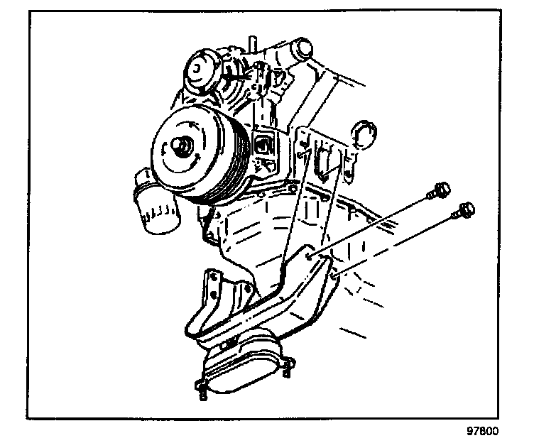
5. Remove the bolts retaining the engine mount bracket to the engine.
6. Remove the engine mount from the bracket.
7. Replace the engine mount bracket with P/N 10321856.
8. Install the engine mount to the bracket.
Tighten
Tighten the engine mount upper nuts to 78 N.m (58 lb ft).
9. Install the engine mount bracket with the engine mount to the engine.
Tighten
Tighten the engine mount bracket bolts to 102 Nm (75 lb ft).
Important:
^ Replace the frame mounting bolts, P/N 10403403.
^ Only replace the frame insulators if necessary, front upper P/N 10402880, front lower P/N 10402882, rear upper P/N 10402881, and rear lower P/N 10299475.
10. Replace the frame, P/N 10322679. Refer to Frame Replacement in Body and Accessories in the Service Manual (SI2000 Document ID # 793554).
11. Align the vehicle. Refer to Wheel Alignment in the Service Manual (SI2000 Document ID # 729569).
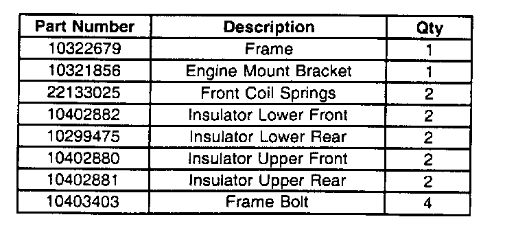
Parts Information
Parts are currently available from GMSPO.
Warranty Information
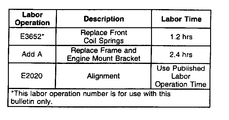
For vehicles repaired under warranty, use the table.

Disclaimer