Trim Height Sensor and Bracket Replacement
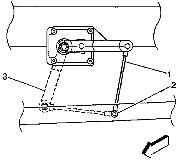
REMOVAL PROCEDURE
Notice: When a procedure requires disconnection of the automatic level control sensor from the tie rod, always disconnect the link at the tie rod (not at the automatic level control sensor arm), and take care not to bend or break the automatic level control sensor arm. When reconnecting the link to the tie rod, make sure that the sensor arm and link are properly oriented. Improper orientation will prevent the ALC system from operating properly and can result in damage to the automatic level control sensor.
CAUTION: Before removing or installing any electrical unit or when a tool or equipment could easily come in contact with "live" exposed electrical terminals, disconnect the negative battery cable to help prevent personal injury and/or damage to the vehicle or components. Unless instructed otherwise, the ignition switch must be in the "OFF" or "LOCK" position.
1. Remove the battery ground cable.
2. Raise and support the vehicle.
3. Remove the Automatic Level Control sensor connector.
4. Remove the Automatic Level Control sensor (4) from under the body rail.
Important: Do NOT bend or break the sensor arm when you remove the link.
5. Remove the Automatic Level Control sensor link (1) from the tie rod (2) ball stud.
6. Remove the bolts/screws which retain the Automatic Level Control sensor.
7. Remove the Automatic Level Control sensor (4) from the vehicle.
8. Remove the bolts/screws to the Automatic Level Control sensor bracket.
9. Remove the sensor electrical harness clip and bracket from the sensor.

INSTALLATION PROCEDURE
1. Install the bracket and sensor electrical harness clip to the ALC sensor (4).
NOTICE: Always use the correct fastener in the proper location. When you replace a fastener, use ONLY the exact part number for that application. The manufacturer will call out those fasteners that require a replacement after removal. The manufacturer will also call out the fasteners that require thread lockers or thread sealant. UNLESS OTHERWISE SPECIFIED, do not use supplemental coatings (paints, greases, or other corrosion inhibitors) on threaded fasteners or fastener joint interfaces. Generally, such coatings adversely affect the fastener torque and joint clamping force, and may damage the fastener. When you install fasteners, use the correct tightening sequence and specifications. Following these instructions can help you avoid damage to parts and systems.
2. Install the bolts/screws to the ALC sensor bracket.
Tighten the bolts/screws to 4 Nm (35 inch lbs.).
3. Install the ALC sensor (4) to the vehicle.
4. Install the bolts/screws retaining the ALC sensor.
Tighten the bolts/screws to 10 Nm (89 inch lbs.).
Important: Do NOT bend or break the sensor arm when you connect the link.
5. Install the ALC sensor link (1) to the tie rod (2) ball stud.
6. Install the ALC sensor connector to the underbody rail.
7. Install the ALC sensor connector.
8. Lower the vehicle.
9. Install the battery ground cable.