Ride Height Sensor: Adjustments
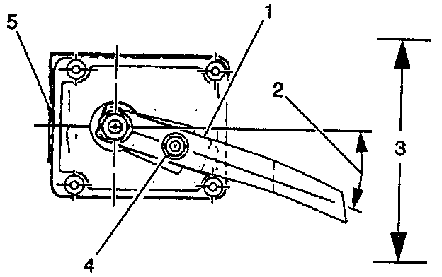
Use the following procedure in order to manually adjust the height sensor in-trim zone:
1. Load 400 lbs or more into the rear of the passenger compartment (enough load to activate the compressor), distributed evenly from left to right.
2. Raise and suitably support the vehicle. Ensure that the vehicle is roughly level and supported by the rear wheels or axle.
Notice: When diagnosis or repair requires raising the vehicle on a hoist, it is important that the rear axle remains in the normal trim height position at all times. Therefore, the hoists should support the rear wheels or axle housing. Use two additional jack stands to support the rear axle when a frame contact hoist is used or damage to the auto level control air compressor could occur.
3. Inspect the height sensor for damage. Ensure that the height sensor link is properly connected to the tie rod and height sensor arm.
4. Turn the vehicle to RUN and then to OFF. Wait for approximately one minute for the arc to complete.
5. Measure the D dimension at the rear axle on both the right and the left hand side.
6. The average D dimension should be 125-140 mm (4.9-5.5 inch). If the average dimension D dimension is within this range, do not adjust the height sensor. If the D dimension is not within this range, adjust the height sensor as follows:
6.1. Loosen the height sensor arm adjustment bolt.
6.2. In order to raise the vehicle, move the plastic portion of the height sensor arm upwards. In order to lower the vehicle, move the plastic portion of the height sensor arm downwards. Rotating the plastic portion of the height sensor arm one degree will change the D dimension by 4 mm (0.16 inch).
NOTICE: Always use the correct fastener in the proper location. When you replace a fastener, use ONLY the exact part number for that application. The manufacturer will call out those fasteners that require a replacement after removal. The manufacturer will also call out the fasteners that require thread lockers or thread sealant. UNLESS OTHERWISE SPECIFIED, do not use supplemental coatings (paints, greases, or other corrosion inhibitors) on threaded fasteners or fastener joint interfaces. Generally, such coatings adversely affect the fastener torque and joint clamping force, and may damage the fastener. When you install fasteners, use the correct tightening sequence and specifications. Following these instructions can help you avoid damage to parts and systems.
6.3 Tighten the height sensor arm adjustment.
Tighten the height sensor arm adjustment bolt to 5 Nm (44 inch lbs.).
6.4. In order to verify that the height sensor is adjusted properly, repeat steps 4-6.