Connecting Rod Bearing: Service and Repair
REMOVAL PROCEDURE^ TOOLS REQUIRED
- J 5239 Connecting Rod Bolt Guide Set
1. Remove the oil pan.
2. Remove the oil pump.
3. Remove the crankshaft oil deflector.
4. Turn the crankshaft until the piston and rod assembly to be serviced is at Bottom Dead Center (BDC).
IMPORTANT: Place matchmarks or numbers on the connecting rod and connecting rod caps. The connecting rod caps must be assembled to their original connecting rod.
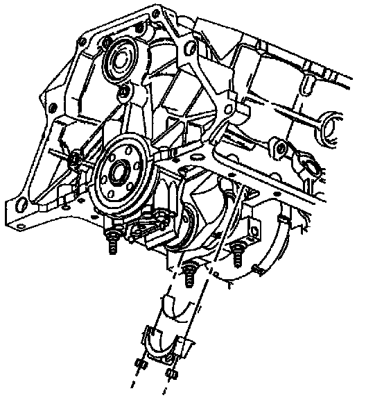
5. Remove the connecting rod nuts.
6. Remove the connecting rod cap.
7. Remove the lower connecting rod bearing.
NOTICE: Install thread protector in order to avoid damage to the crankshaft journal.
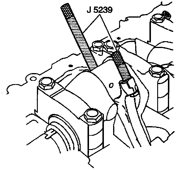
8. Install the J 5239.
9. Push the piston and connecting rod up the cylinder in order to gain access to the upper connecting rod bearing.
10. Remove the upper connecting rod bearing.
11. Wipe oil from the connecting rod bearings and crankshaft connecting rod journal.
12. Inspect the connecting rod bearings.
13. Inspect the connecting rod cap and connecting rod.
14. Inspect the crankshaft connecting rod journal.
INSTALLATION PROCEDURE
^ TOOLS REQUIRED
- J 5239 Connecting Rod Bolt Guide Set
- J 36660 Torque Angle Meter
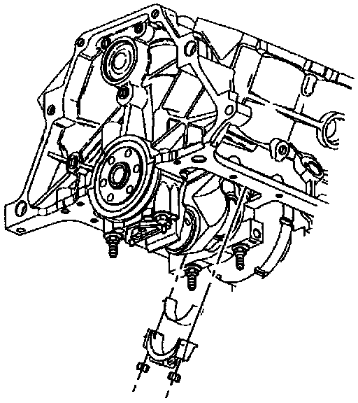
1. Install upper connecting rod bearing into connecting rod.
2. Coat the inside surfaces of the upper connecting rod bearing with new engine oil.
3. Using the J 5239 pull the piston and rod assembly down to the crankshaft.
4. Remove the J 5239.
5. Install the lower connecting rod bearing into the connecting rod cap.
6. Coat the inside surfaces of the lower connecting rod bearing with new engine oil.
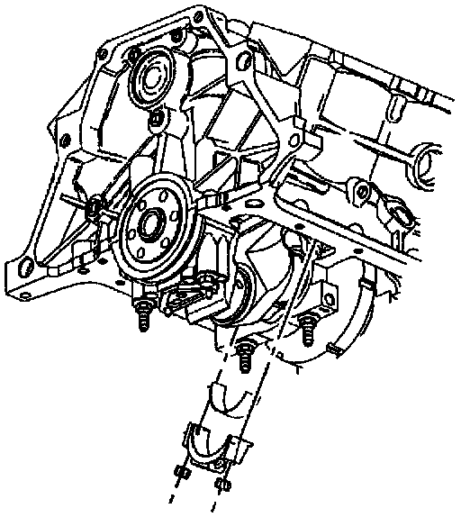
7. Install the connecting rod cap with lower connecting rod bearing.
8. Install the connecting rod nuts.
^ Tighten the connecting rod nuts to 20 Nm (15 ft. lbs.). Evenly turn the nuts an additional 75 degrees using the J 36660.
9. Measure the connecting rod clearance using the following procedure:
9.1. Install all connecting rod bearings.
9.2. Lightly tap each connecting rod parallel to the crankpin in order to make sure the connecting rods have clearance.
9.3. Measure the side clearance between the connecting rod caps using a feeler gage, or dial indicator.
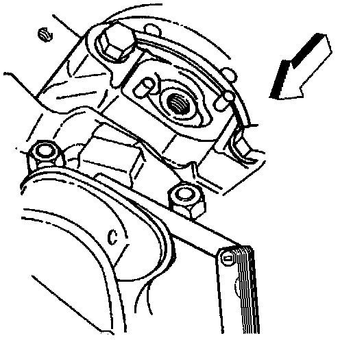
10. Install the crankshaft oil deflector.
11. Install the oil pump.
12. Install the oil pan.