Video Channel(s) Inoperative - All Modes
Diagnostic Trouble Code Chart:
Wiring Schematics:
CIRCUIT DESCRIPTION
The Video Entertainment System (VES) sends stereo video audio channels to the Second and Third Seat Audio (SSA/TSA) controls, which is available through the headphone jacks.
NOTE: The SSA/TSA control must be set to VCR in order to listen to the video audio channels. The VES also uses the rear speakers for video audio only when the radio and the Rear Seat Audio (RSA) control are off.
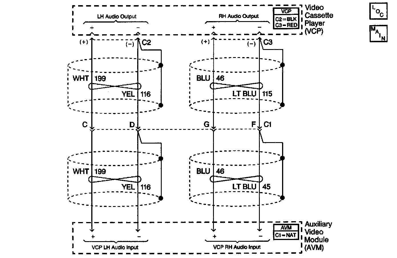
The Auxiliary Video Module (AVM) receives stereo audio channels from the Video Cassette Player (VCP) connectors C2 and C3. The AVM amplifies the audio signal from the VCP, and then provides two outputs: one at headphone level, and another one at speaker level.
DIAGNOSTIC AIDS
^ Check for the following conditions:
- A worn or defective VHS tape with a muted or defective audio channel
- Check for an open in CKT 116 and/or 199 (when the left audio channel is inoperative)
- Check for an open in CKT 46 and/or 115 (when the right audio channel is inoperative)
- Faulty AVM
- Faulty VCP
^ An intermittent failure may be very difficult to detect and to diagnose accurately. Faulty electrical connections or wiring causes most intermittent problems. When an intermittent condition is suspected, check the suspected circuits for the following conditions:
- Poor mating of connector halves or backed out terminals
- Improperly formed or damaged terminals
- Wire chafing
- Poor wire to terminal connections
- Dirty or corroded terminals
- Damage to connector bodies
- Wire broken inside the insulation
TEST DESCRIPTION
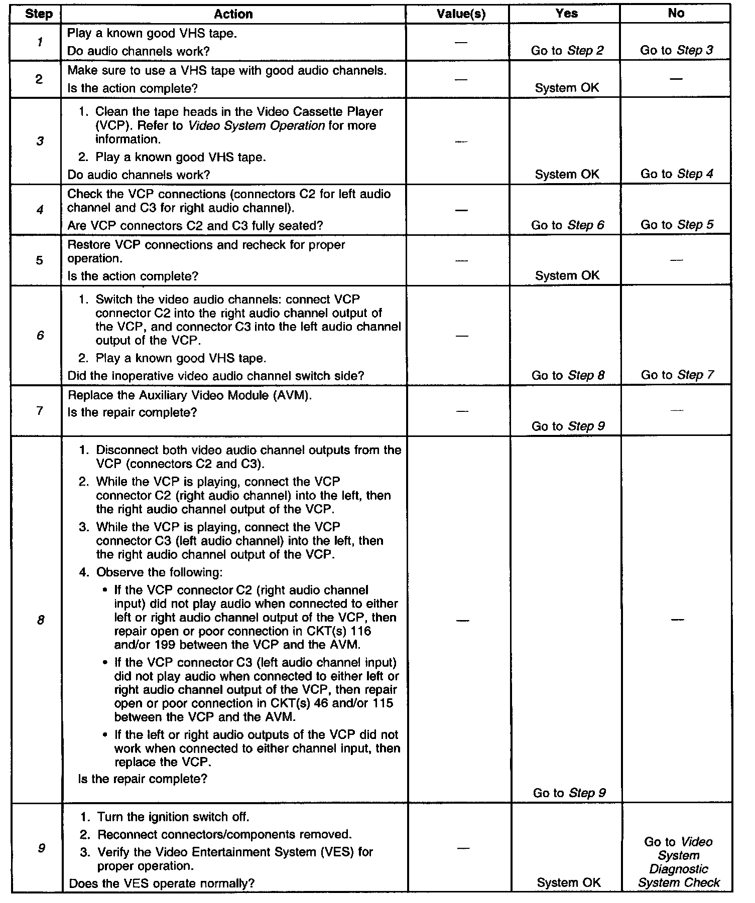
The number(s) below refer to the step number(s) on the diagnostic table.
1. Checks for a faulty VHS tape.
3. Checks for dirty VCP audio play head.
4. Checks for backed out connectors (audio inputs) at the VCP.
6. Determines if the Auxiliary Video Module is faulty.
8. Determines whether the video audio channel input circuits are open or the VCP is faulty.
9. Verifies repairs made to the VES.