DTC 08
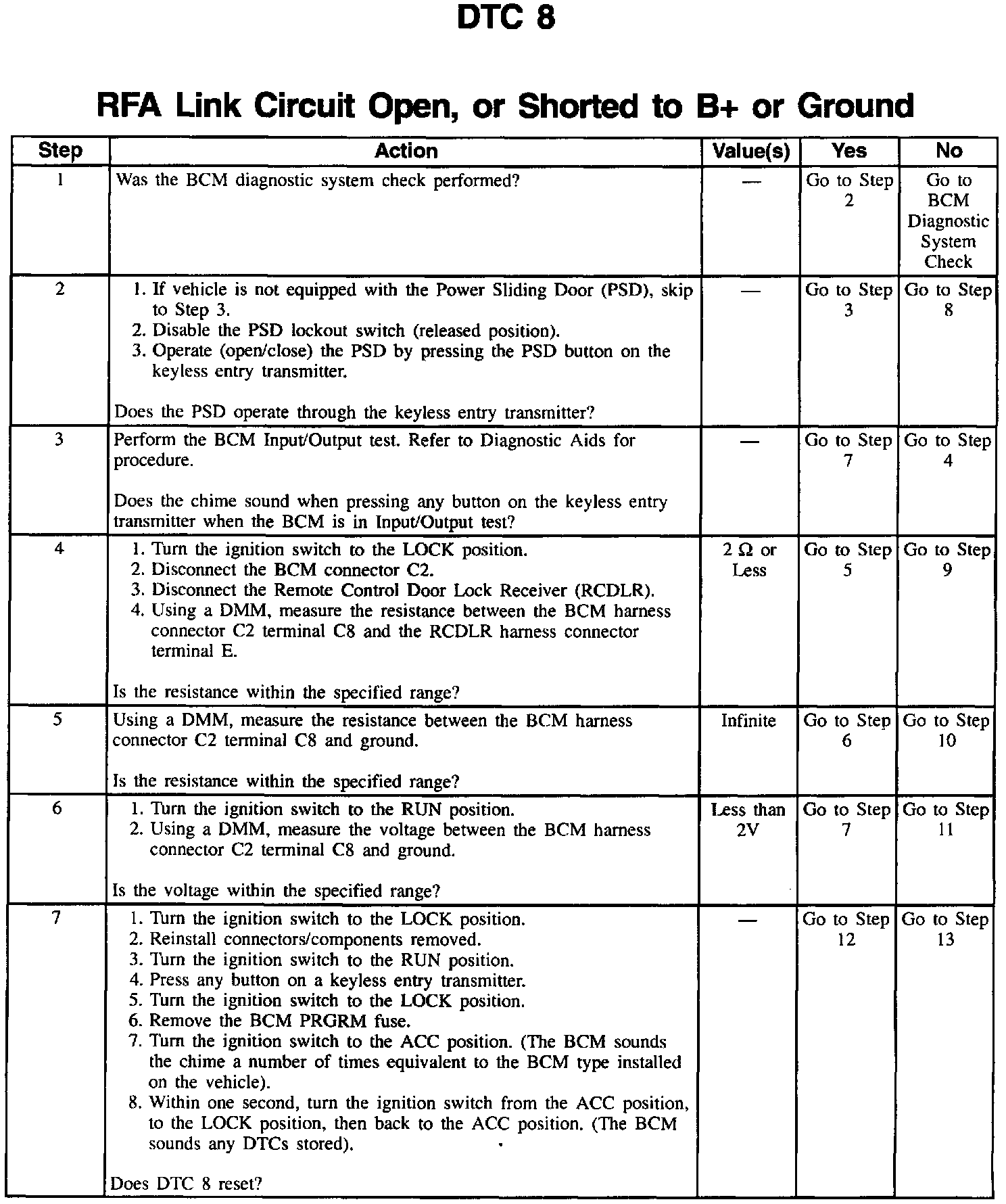
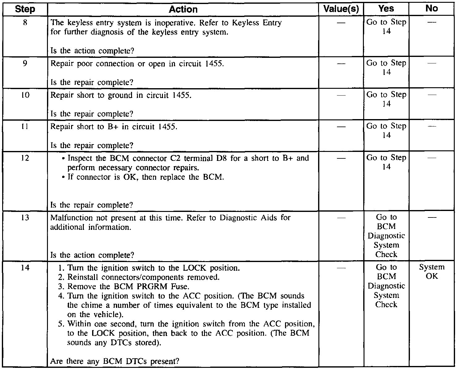
DTC8 RFA Link Circuit Open, Or Shorted To B+ Or Ground:
CIRCUIT DESCRIPTION
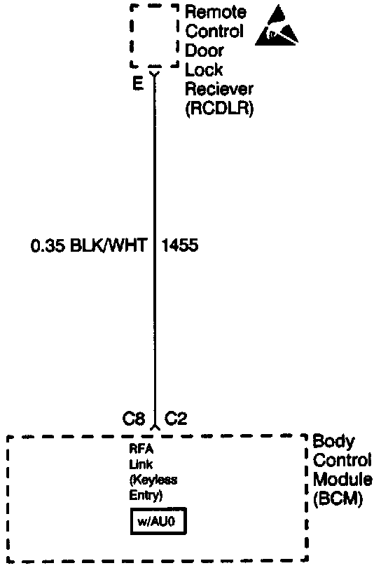
When pressing any button on the keyless entry transmitter. the transmitter sends a radio frequency signal to the Remote Control Door Lock Receiver (RCDLR).
The RCDLR interfaces with the Body Control Module (BCM) to perform door lock/unlock functions. On vehicles equipped with the content theft deterrent (BCM type 4) the RCDLR interfaces with the BCM to perform alarm functions.
The RCDLR sends a digital message to the BCM through circuit 1455. The RCDLR determines the type of message sent to the BCM based on the button pressed on the keyless entry transmitter.
Then, the BCM determines what functions to perform (door lock/unlock. alarm) based on the message(s) received from the RCDLR.
CONDITIONS FOR SETTING THE DTC
The BCM detects an open. a short to B+. or a short to ground in circuit 1455.
ACTION TAKEN WHEN THE DTC SETS
^ The BCM sets Diagnostic Trouble Code (DTC) 8.
^ The keyless entry system remains inoperative. Note: The power sliding door may still be operational because the RCDLR operates the power sliding door directly, without using the BCM.
CONDITIONS FOR CLEARING THE DTC
^ An open, a short to B+, or a short to ground in circuit 1455 is no longer present between the BCM and the RCDLR.
^ After repairs are completed, DTC is cleared by performing the Clearing Diagnostic Trouble Codes (DTCs) procedure.
DIAGNOSTIC AIDS
^ Check for an open, a short to B+, or a short to ground in circuit 1455.
^ A faulty Remote Control Door Lock Receiver (RCDLR.)
^ Try performing the tests shown while moving wiring and connectors. This can often cause the malfunction to appear.
BCM INPUT/OUTPUT TEST PROCEDURE
1. Turn off the I/P dimmer switch.
2. Turn the ignition switch to the LOCK position.
3. Remove the BCM PRGRM fuse.
4. Turn the ignition switch to the ACC position.
^ The BCM sounds the chime a number of times equivalent to the BCM type installed on the vehicle.
5. Within 1 second, turn the ignition switch from the ACC position, to the LOCK position, then back to the ACC position.
^ The BCM sounds any DTCs stored.
6. Turn the I/P dimmer switch to the DOME position.
The BCM entered the Input/Output test. The BCM Input/Output consists of:
^ Test 1: De-energizes circuits 1393 and 328 (protected courtesy light output).
^ Test 2: Energizes circuits 1393 and 328.
^ Test 3: Grounds circuit 690 (courtesy lights control).
^ Test 4: Energizes the theft deterrent relay for one second by grounding circuit 301, turning on the exterior lights (BCM type 3 and 4 only).
^ Test 5: Energizes the horn relay for 25 ms by grounding circuit 28, sounding the horn (BCM type 4 only).
^ Test 6: Turns on the security indicator lamp by grounding circuit 749 (BCM type 4 only).
^ Test 7: Turns off the security indicator lamp by opening circuit 749 (BCM type 4 only).
The BCM runs the Input/Output test in numerical order.
To move to the next test, cycle the I/P dimmer switch from DOME, to off, back to DOME. The BCM sounds the chime a number equivalent to the Input/Output test number above. The Input/Output test sequence repeats until the ignition switch is turned to the LOCK position.
When the BCM is performing the Input/Output test, the BCM sounds the chime when any of the keyless remote transmitter buttons is pressed (BCM type 3 and 4 only). This test checks that the BCM is receiving commands from the keyless entry transmitter via the RCDLR.
TEST DESCRIPTION
Numbers below refer to the step numbers on the diagnostic table.
1. Always perform the BCM diagnostic system check before attempting to diagnose this DTC.
2. Determines whether the malfunction is related to a fault within the RCDLR and not due to a faulty circuit 1455.
3. Determines whether the malfunction is intermittent and not currently present.
4. Checks for an open in circuit 1455.
5. Checks for a short to ground in circuit 1455.
6. Checks for a short to B+ in circuit 1455.
7. Determines whether the malfunction is intermittent and not related to a faulty BCM.