Low Engine Coolant Indicator Inoperative
- Disconnect engine coolant level indicator switch connector. See COMPONENT LOCATIONS
table. Using DVOM, check resistance between engine coolant level indicator switch connector terminal "B" (Black wire) and ground. If resistance is less than 2 ohms, go to step 3). If resistance is not less than 2 ohms, go to next step.
- Check for open or high resistance in circuit No. 150 (Black wire) between engine coolant level indicator switch and splice pack SP100 (located in forward lighting harness). Repair as necessary and recheck system operation. If circuit is okay, replace splice pack SP100.
- Reconnect engine coolant level indicator switch connector. Disconnect underhood electrical center connector C3. See Fig 1
. Move engine coolant level indicator switch to CLOSED position. Using DVOM, check resistance between underhood electrical center connector C3, terminal D9 (Yellow/Black wire) and ground. If resistance is less than 2 ohms, go to step 5). If resistance is not less than 2 ohms, go to next step.
- Check for open or high resistance in circuit No. 68 (Yellow/Black wire) between underhood electrical center connector C3 and engine coolant level indicator switch. Repair as necessary and recheck system operation. If circuit is okay, replace engine coolant level indicator switch. Recheck system operation.
- Reconnect underhood electrical center connector C3. Disconnect instrument cluster connector. Using DVOM, check resistance between instrument cluster connector terminal A8 (Yellow/Black wire) and ground. If resistance is less than 2 ohms, go to step 7). If resistance is not less than 2 ohms, go to next step.
- Check for open or high resistance in circuit No. 68 (Yellow/Black wire) between instrument cluster connector and underhood electrical center connector C2, terminal F7. Repair as necessary and recheck system operation. If circuit is okay, replace underhood electrical center. Recheck system operation.
- Replace IPC. See INSTRUMENT PANEL CLUSTER
under REMOVAL & INSTALLATION. Recheck system operation.
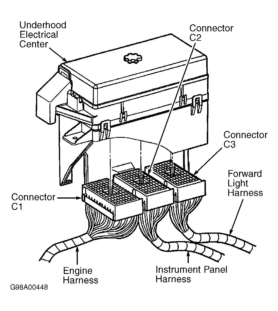 Courtesy of GENERAL MOTORS CORP.