Universal Joint: Service and Repair
DISASSEMBLY PROCEDURE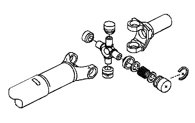
^ Tools Required
- J 9522-3 U-Joint Bearing Separator
- J 9522-5 U-Joint Bearing Spacer Remover
NOTICE: Never clamp propeller shaft tubing in a vise. Clamping propeller shaft tubing in a vise could dent or deform the tube causing an imbalance or unsafe condition. Always clamp on one of the yokes and support the shaft horizontally. Avoid damaging the slip yoke sealing surface. Nicks may damage the bushing or cut the lip seal.
IMPORTANT: Nylon injected ring universal joints cannot be reassembled. Replace nylon injected ring universal joints with external snap ring universal joints.
When reassembling a propeller shaft, always install a complete propeller shaft universal joint service kit.
This kit includes the following components:
^ One pregreased spider (8)
^ Four service bearing caps with seals (7)
^ One needle roller bearing (4)
^ Delrin round washers (3)
^ Delrin flat washers (5)
^ Grease
^ Four retainer rings (2)
Ensure that the seals (7) are in place on the service bearing caps (1) during handling. The seals will hold the needle roller bearings (4) in place during handling.
IMPORTANT: There are no bearing retainer grooves in production bearing caps. Production bearing caps cannot be reused.
1. Support the propeller shaft in a horizontal position that is aligned with the base plate of a press.
2. Place the universal joint so that the lower ear of the shaft yoke is supported on a 29 mm (1.125 inch) socket (2).
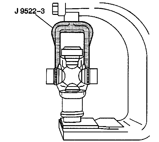
3. Use the following procedure in order to remove the lower bearing cap from the yoke ear:
3.1. Place the J 9522-3 on the open horizontal bearing cap.
3.2. Press the lower bearing cap out of the yoke ear.
This process shears the nylon injected ring on the lower bearing cap.
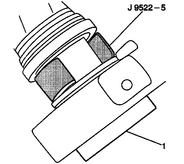
4. If the bearing cap (1) is not completely removed, use the following steps in order to completely remove the bearing cap:
4.1. Lift the J 9522-3
4.2. Insert the J 9522-5 between the seal and the bearing cap (1).
4.3. Press the bearing cap (1) out of the yoke.
5. Rotate the propeller shaft.
5.1. Repeat Step 3 in order to shear the opposite nylon injected ring.
5.2. Repeat Step 4 in order to remove the opposite bearing cap from the yoke.
6. If the front universal joint is being replaced, use the above procedure in order to remove the two bearing caps from the propeller shaft slip yoke.
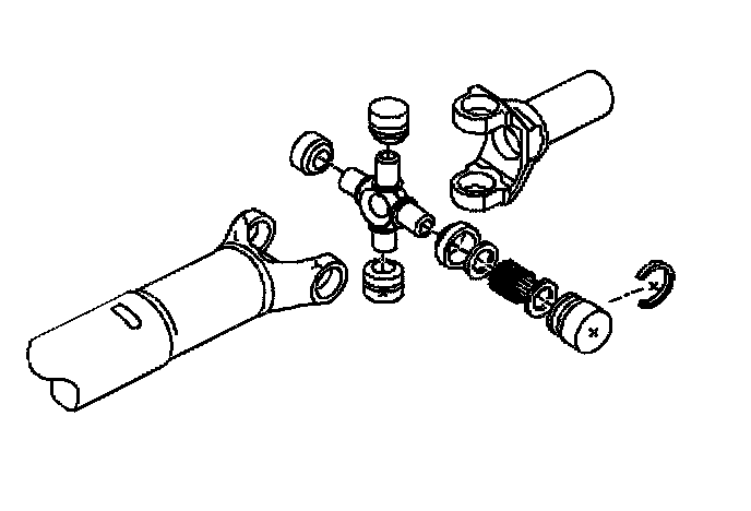
7. Remove the spider from the yoke.
8. Clean the yoke in the area that will hold the retainer ring in order to ensure proper assembly.
9. Clean all of the sheared nylon from the universal joint cup bore.
If the dust seals are loose or damaged, replace the entire universal joint.
IMPORTANT: Do not loosen or damage the dust seals.
When these joints are taken apart, repack the bearing. Lubricate the reservoir at the end of the trunnions with chassis lubricant or linkage joint lubricant.
IMPORTANT: These universal joints are designed for extended life and do not require periodic inspections or lubrication.
10. Remove the U-joint spider bearing retainer rings. If the retainer ring does not snap readily out of the grooves, lightly tap the end of the bearing cap in order to relieve the pressure against the retainer ring. After relieving the pressure, remove the retainer ring.
11. Support the propeller shaft in a horizontal position that aligns with the base plate of a press.
12. Place the universal joint so the ear of the yoke is supported on a 28.6 mm (1.125 inch) socket (2).
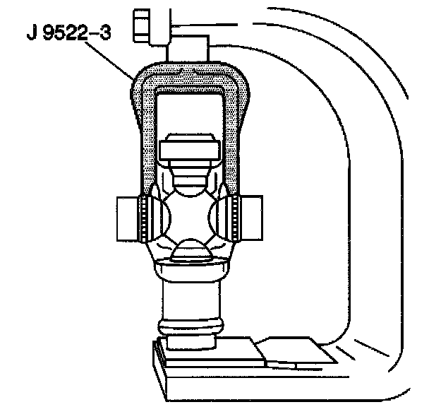
13. Use the following procedure in order to remove the lower bearing cap from the yoke ear:
13.1. Place the J 9522-3 on the open horizontal bearing cap.
13.2. Press the lower bearing cap out of the yoke ear.
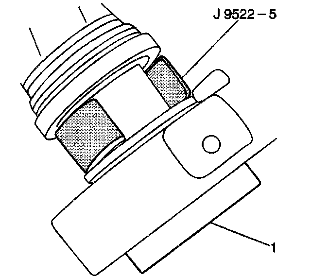
14. If the bearing cap (1) is not completely removed, use the following steps in order to completely remove the bearing cap:
14.1. Lift the J 9522-3.
14.2. Insert the J 9522-5 between the seal and the bearing cap (1).
14.3. Press the bearing cap (1) out of the yoke.
15. Rotate the propeller shaft.
Press the opposite bearing cap out of the yoke.
16. Remove the spider from the yoke.
ASSEMBLY PROCEDURE
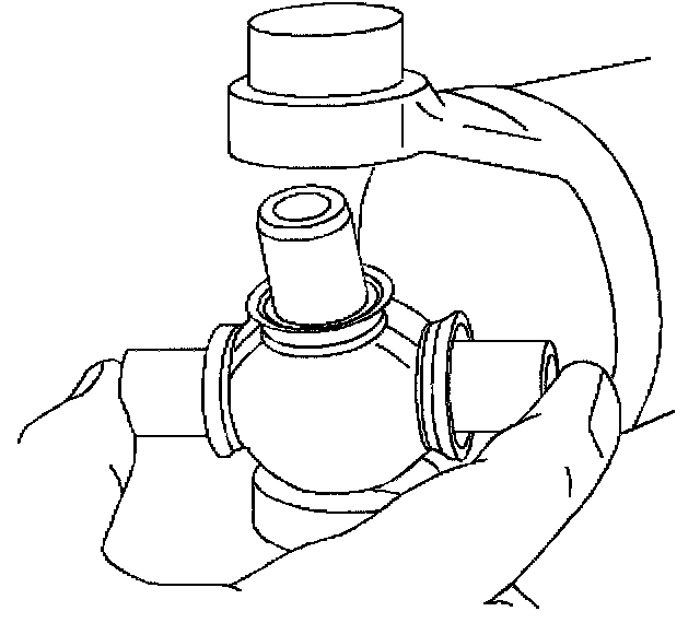
1. Install one bearing cap partially into one side of the yoke.
Rotate the yoke so that this yoke ear is on the bottom.
2. Insert the J 9522-3 in order to seat the trunnion in the bearing cap.
3. Repeat Steps 1 and 2 in order to partially install the opposite bearing cap.
4. Inspect both trunnions in order to ensure their straight positioning into the bearing caps (1).
5. Press against the two opposite bearing caps while working the spider in order to ensure free movement of the trunnions in the bearings.
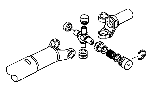
6. Inspect the needle roller bearing for binding.
If binding exists, one or more of the needle roller bearings may have tipped under the end of the relevant trunnion.
7. Stop pressing on the bearing caps when one bearing retainer groove clears inside of the yoke.
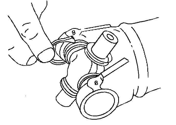
8. Press the U-joint spider bearing retainer ring into place.
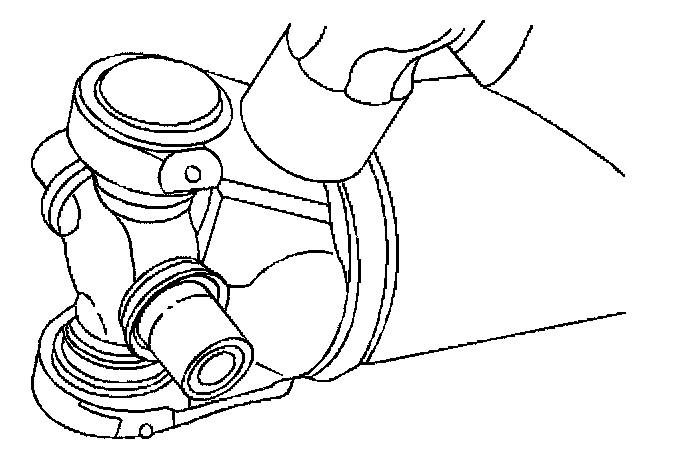
9. Continue pressing on the retainer ring until the opposite side of the ring can be snapped into place.
If necessary, strike the yoke with a hammer in order to facilitate seating of the retainer rings. (Striking the yoke with a hammer slightly springs the yoke ears.)
10. Repeat the above procedure for the other half of the universal joint.