Diagnosis By Symptom - Key Reminder
REMINDER CONTINUES TO OPERATE WITH KEY OUT, BUT STOPS WHEN DRIVER'S DOOR IS CLOSEDInspect
^ Chips, foreign material in lock cylinder bore.
^ Sticky lock cylinder actuator tip.
Checking Reminder Switch:
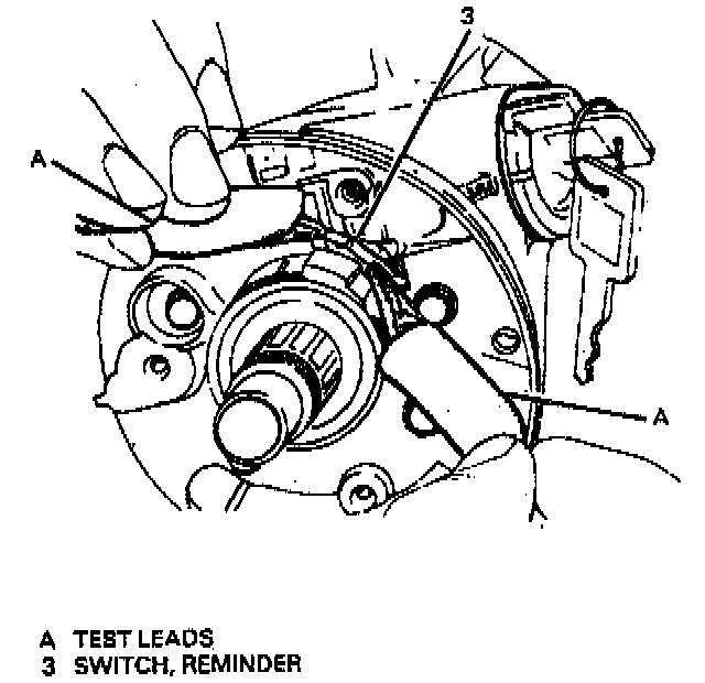
^ Damaged or broken reminder switch (3).
REMINDER DOES NOT SOUND WITH KEY FULLY INSERTED IN LOCK CYLINDER AND THE DRIVER'S DOOR OPEN
Inspect
NOTICE: If you are using a multimeter to check continuity with voltage present in circuits, be sure to use a voltage setting. A multimeter set on a resistance scale will be damaged by the voltage from live circuits.
1. Reminder to see if power is available.
2. Chassis wiring for open circuit.
Checking Reminder At Chassis Connector:
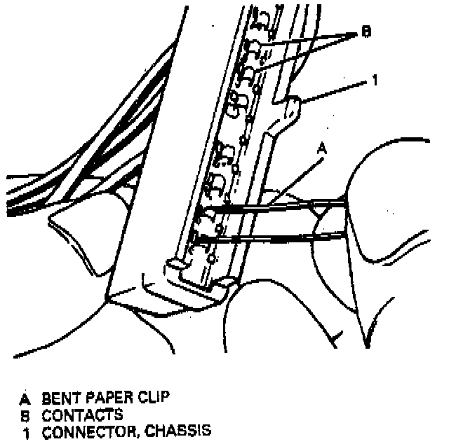
Checking Reminder At Column Connector:
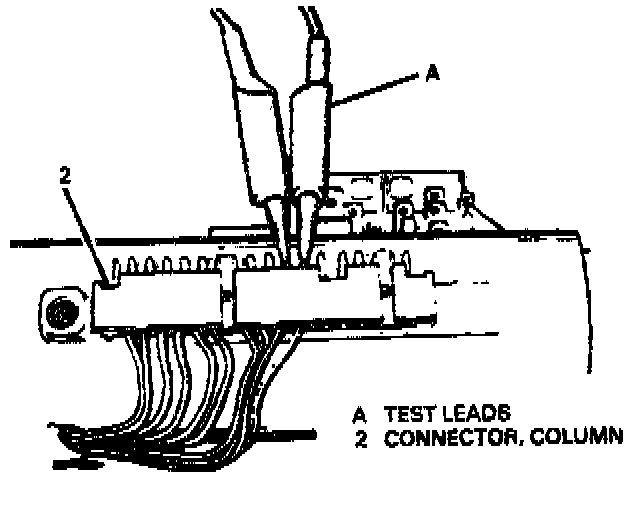
A. Separate chassis connector (1) from column connector (2).
B. Connect female contacts of terminals E and F on chassis connector (1). A bent paper clip will work as a jumper.
^ If reminder sounds, repair chassis wiring.
^ If reminder does not sound, go to step 3.
3. Continuity between male E and F column connector contacts with a multimeter (or test light).
Lock Cylinder Actuator - Key Removed:
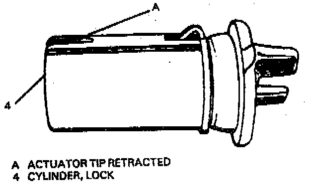
Lock Cylinder Actuator - Key In Place:
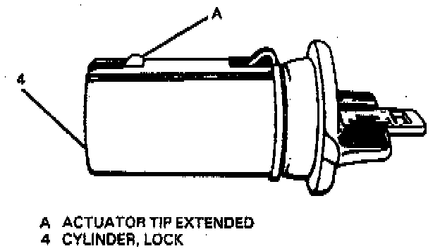
A. Push key all the way into lock cylinder (4).
^ If there is continuity when key is in, and off when key is out, function is normal.
^ If there is no continuity, fault is in column. Go to step 4.
4. Probes of reminder switch (3) to ensure good contact with pads on signal switch.
A. Disassemble upper end of column until turn signal switch mounting bolts/screws have been removed.
B. Lift turn signal switch to gain access to probes.
C. Bend probes, if needed, then replace turn signal switch and tighten three bolts/screws.
D. Check function as in step 3.
5. Turn signal switch wiring for short or fault.
A. Connect male contacts of terminals E and F of column connector (2) with a jumper.
Checking Reminder Switch:
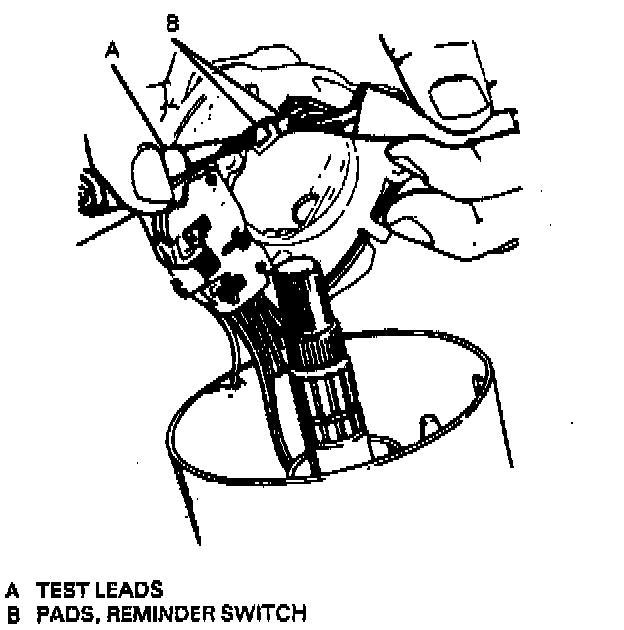
B. Check key reminder switch pads on turn signal switch with multimeter.
^ If there is continuity, function is normal.
^ If there is no continuity, replace turn signal switch.
Checking Key Reminder Switch Continuity:
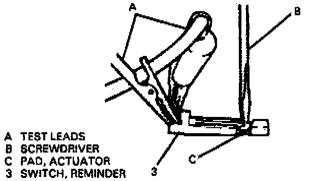
6. Continuity of check key reminder switch probes, if problem has not been found.
A. Connect a multimeter to probes on reminder switch (3).
B. Fully insert and remove key from lock cylinder (4).
^ If there is continuity when key is in lock cylinder (4) and no continuity when key is out, function is normal. Retrace diagnostic steps starting at step 3.
^ If there is no continuity, fault is in lock cylinder (4) or reminder switch (3).
7. Lock cylinder (4) for chips, burrs, or foreign material that may prevent actuator tip function.
A. Key must be removed, or lock cylinder (4) must be in RUN position, before lock cylinder can be removed.
B. Remove chips, burrs or foreign material.
C. Reassemble and recheck
8. Lock cylinder for damage.
A. With lock cylinder removed, push key all the way in, turn to RUN position and then remove it.
^ The lock cylinder actuator tip should extend and retract smoothly. Total extension of tip should be 1.27 mm (0.050 inch).
^ If not, replace lock cylinder (4). Reassemble and recheck per step 4.
9. Reminder switch (3) if it appears good but will not operate.
A. Connect multimeter leads to reminder switch probes on reminder switch.
B. Press on actuator pad until switch points touch.
C. If there is no continuity, replace reminder switch.
Checking Contact Gap:
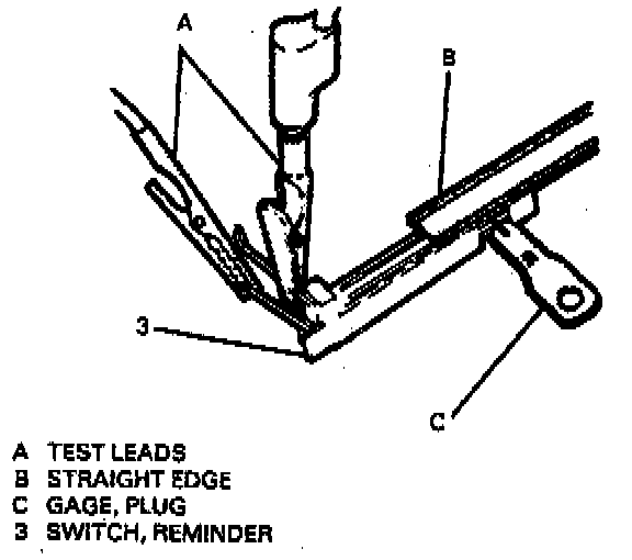
10. Reminder switch contact gap.
A. Connect multimeter leads to reminder switch probes on reminder switch (3).
B. Press a 0.76 mm (0.030 inch) wire type plug gage with a flat piece of stock onto actuator pad.
Decreasing Switch Contact Gap:
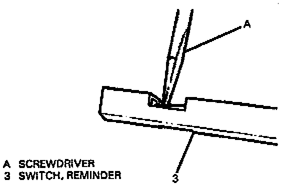
^ If contact is not made (no continuity), decrease switch contact gap until positive contact is made.
11. Reminder switch contact gap, with positive contact gap set at 0.76 mm (0.030 inch) as outlined above.
A. Use a 0.63 mm (0.()25inch) plug gap wire beneath flat stock.
Increasing Switch Contact Gap:
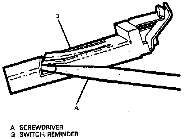
^ If contact is made (continuity), increase switch contact gap.
B. Reminder switch (3) is set properly when switch contact will touch 0.76 mm (0.0030 inch) wire but not 0.63 mm (0.025 inch) wire.
REMINDER KEEPS OPERATING WITH KEY IN LOCK CYLINDER, DRIVER'S DOOR OPEN OR CLOSED; CEASES WHEN KEY IS REMOVED
Inspect
^ Misadjusted or inoperative door jamb switch on driver's side.
^ Shorted wire from signal switch to door jamb switch.
A. This condition indicates lock cylinder (4) or reminder switch (3) is at fault. To verify, check for continuity at E and F male column connector contacts, with key removed from lock cylinder (4).
^ If continuity exits, fault is in column.
B. Insert key into lock, then turn lock toward START position.
^ If reminder stops when key is in RUN position or when it is turned past RUN toward START, problem is a sticky lock cylinder actuator.